Wireless Motor Driver Shield Hookup Guide
 Nick Poole,
  Shawn Hymel
Hardware Overview
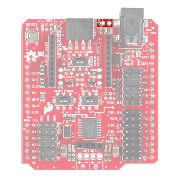
The Wireless Motor Driver Shield has a number of connectors, switches, and ports for you to use. Let's take a look at each one.
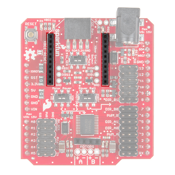
XBee Port
At the top of the board, you will find two rows of headers meant to accept an XBee module. The XBee UART is connected to digital pins 0 and 1 or analog pins A0 and A1, depending on the position of the XBee selector switch.
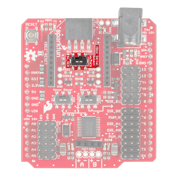
XBee Pins Select Switch
The selector switch underneath the XBee port allows you to choose which pins to use to communicate to the XBee module. The table below shows which pins on the Arduino the XBee RXI and TXO pins are connected to, depending on the switch's position. If you use SW_SER (pins A0 and A1), you'll need to use the Software Serial library.
So, if you plan to use HW_SER to communicate to the XBee, you'll need to switch it to SW_SER when uploading new code. When code has finished uploading to the Arduino, the switch will need to be flipped back to the HW_SER side to communicate to the XBee.
| Position | XBee RXI | XBee TXO |
|---|---|---|
| HW_SER | 0 | 1 |
| SW_SER | A0 | A1 |
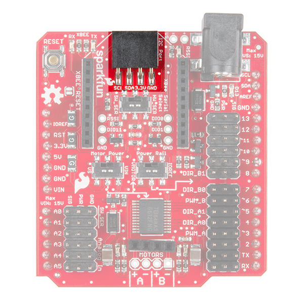
I2C Port
Under the XBee footprint, you'll also find a 4-pin female header that breaks out the Arduino's I2C lines. You can use this to attach various sensors to your project.
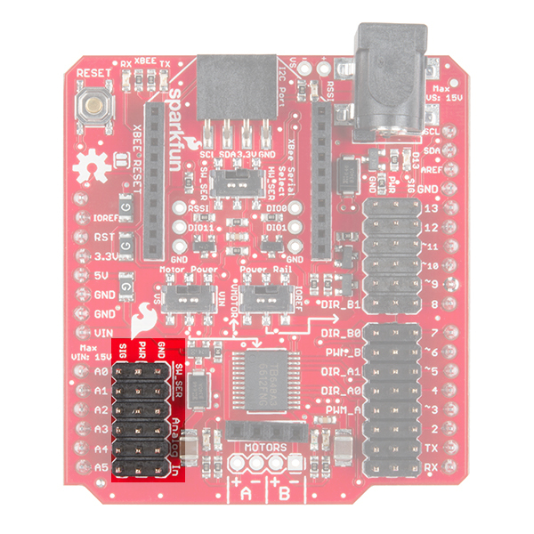
Analog Input Pins
On the left side of the shield, you'll find pins A0 through A5 broken out to headers with power and ground pins for each analog pin. Be aware that if you select SW_SER on the XBee switch, pins A0 and A1 will be used to connect to the XBee's RXI and TXO, respectively.
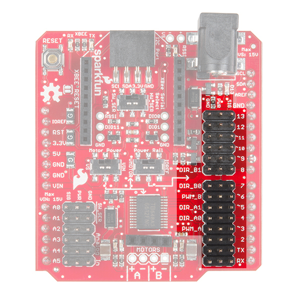
Digital Pins
On the right side, you'll see digital pins 0 through 13 broken out to headers with a power and ground pin for each pin. These are configured this way to allow you to easily connect servos. Note that the power pins can be connected to IOREF, VIN, or the Shield's power jack, depending on the position of the 2 power switches.
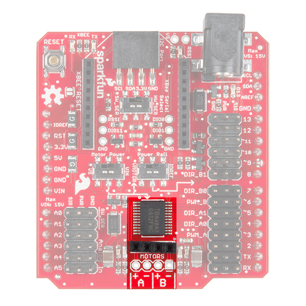
Motor Driver and Output
At the bottom of the Shield, you'll find a TB6612FNG motor driver and a 4-pin header for connecting any number of DC motors. The unpopulated holes are spaced 0.100 inch apart and available for soldering wires from your motor(s).
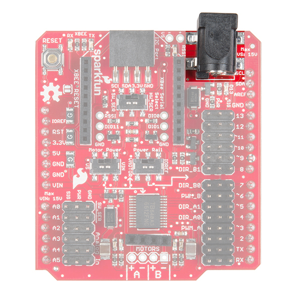
Power Jack
Often, driving motors from the Arduino's power supply (even VIN) will cause the voltage to dip and possibly reset your Arduino. To help with this issue, the power jack on the top-right of the Shield will accept a 5.5 x 2.1mm power plug from a variety of wall adapters and battery packs.
Note that you will need to set the Motor Power switch to VS to power the motors from the power jack. If you also set the Power Rail switch to VMOTOR, then the power jack will be connected to the PWR rail on the digital pins (e.g. to power servos).
Additionally, this power jack will not power the Arduino. It is intended to provide a power supply to your motors separate from your Arduino.
In addition to the power jack, the VS pins are broken out next to the barrel jack connector as "+" and "-".
 |
 |
| Add Electrical Tape where the Arduino Uno's USB Connector is Exposed on the Top | Add Electrical Tape where the External VS Power Pins are Exposed on the Bottom |
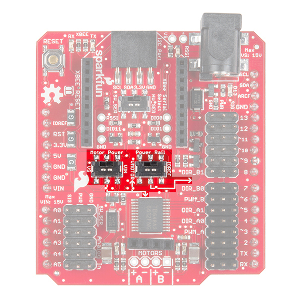
Power Switches
In the middle of the board are 2 switches that can be used to set how power is distributed to the digital PWR rail and motor driver. The Motor Power switch allows you to select between VS (power jack) and VIN (from Arduino) to supply power to the motors (labeled VMOTOR). The Power Rail switch allows you to select between IOREF (from Arduino) and VMOTOR (output of the Motor Power switch) to power the PWR pins on the digital headers.
| Motor Power Switch Position | Power Rail Switch Position | Motor Driver is connected to... | Digital PWR pins are connected to... |
|---|---|---|---|
| VS (power jack) | VMOTOR | VS (power jack) | VS (power jack) |
| VS (power jack) | IOREF | VS (power jack) | IOREF |
| VIN | VMOTOR | VIN | VIN |
| VIN | IOREF | VIN | IOREF |