WAV Trigger Hookup Guide
This Tutorial is Retired!
This tutorial covers concepts or technologies that are no longer current. It's still here for you to read and enjoy, but may not be as useful as our newest tutorials.
 JordanDee
Hardware
Let's take a look at the WAV Trigger's hardware so we can get an idea of where things are and how to use the board.
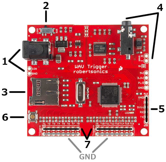
The barrel jack is where you supply power. Alternatively, you can use the nearby VIN and GND via's for supplying power. Either way, any input voltage between 6V and 15V will work.
There is a run/load switch that should always be set to run when you are using the board normally. The board is set to load only when updating the firmware on the ARM processor, which is done before hand at SparkFun. It will only be necessary to put the switch into the load setting if there is a newer version of firmware that you would like to use.
The micro SD card is where your .WAV files and optional configuration file are stored. This micro SD card works well with the board and also includes a micro SD USB Card Reader for transferring the files to/from your computer.
The audio jack is the standard 3.5mm variety and can be used with headphones or speakers of your choice. There is also a 2 pin header for directly wiring and soldering a speaker such as this to the board itself.
The FTDI port is used to program the firmware or can be used with the WAV Trigger's Remote Control App to test triggers using your computer instead of hardware. This way, you can test triggering tracks before soldering hardware to the actual trigger ports. The FTDI port can also be used in conjunction with WAV Trigger's Initialization Editor so when you set a trigger to a non default function such as playing a random track, you can experiment with the trigger's functionality without first having to put the configuration file on the SD card. We will explain more about configuration and testing triggers with the computer later on. To use this port, consider an FTDI Basic.
This button, by default, triggers the first track on the memory card. A future release of the firmware may allow you to modify its functionality.
The row of 16 triggers are the core of this board's utility. These are what we are going to use to start the playing of music or sound effect tracks on the SD card. We'll also learn how to use them for more advanced options like playing a random track or changing volume with the help of a configuration file. Keep in mind, ground connections are closest to the edge of the board and are there for convenience to be used along with a trigger. The actual triggers are the second row from the edge.
Now that we have an understanding of the board's hardware, let's dive a bit deeper into what you can do with it.