WAV Trigger Hookup Guide
This Tutorial is Retired!
This tutorial covers concepts or technologies that are no longer current. It's still here for you to read and enjoy, but may not be as useful as our newest tutorials.
 JordanDee
Example
- The 1GB SparkX SD Card, from our catalog, since it isn't a Class 10 card and can lead to reliability issues.
- SD Cards with a capacity larger than 32GB, since it can be difficult to convert them to the FAT16 or FAT32 file system format with a 32kB file allocation size.
For more information on compatible SD cards, please check out the Robertsonics website:
For this example, make sure you have the sample WAV files already on your micro SD card and have the card in your WAV Trigger board.
Without any configuration at all, you should be able to play each track by connecting the trigger pin with the ground pin. Each track just says the name of the number of the trigger.
Now to test a custom trigger, we need to use the InitMaker application.
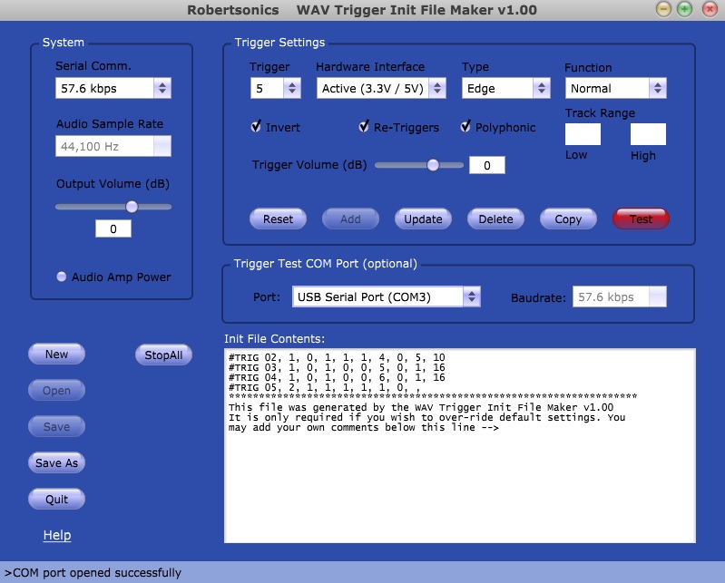
Let's set up a few triggers as an example. Leave trigger 1 with its default settings. Set trigger 2 to play a random track between 5 and 10. First, select random under the "Function" category, then input 5 and 10 under "Track Range". Click the Add button below the settings to add it to the configuration file.
Follow the same procedure to setup a few more triggers. Set trigger 3 to pause and trigger 4 to resume. Also set trigger 5 to the hardware interface of "Active 3.3V/5V" used for when we connect microcontrollers or sensors. Remember to click Add after setting up each trigger to add it to the configuration. If you don't, the settings you input won't be remembered.
Before creating our initialization file, we can test out a custom trigger, if desired, with a USB mini-B cable and an FTDI Basic. Select trigger 2. It should still be set up to play a random track between 5 and 10. Make sure the correct COM port is selected, the one corresponding to your FTDI, then hit the red Test button. Afterwards, activate trigger 2 by connecting its pin to ground. It should randomly play a track between 5 and 10. If this test doesn't work, try reconnecting the FTDI Basic, restarting the InitMaker application, or restarting the WAV Trigger itself.
Now that we have set up triggers 1 through 5, let's save them to a configuration file. Your InitMaker screen should like this if you have it set up the way we described above:
Now, save this configuration using the Save As button in the lower left. The file will need to be called wavtrigr.ini. Put this file on your micro SD card along with the sound files. In case you had trouble making this file, you can download it here.
Also, to demonstrate the pause and resume functions, you may want a longer wav file to play. Here is a longer WAV file you can download if you don't have any of your own currently. Replace the current file that begins with '001' on your SD card with this track. As a side note, you can convert any of your MP3's to WAV's easily with programs like Audacity.
Now that you have your micro SD card loaded with sound files (including new, longer track one) as well as the initialization file we just created, let's test it out to see if it works.
Connect Trigger 1's pin to ground, the first track should play. Connect Trigger pin 3 to ground, and track 1 should pause. Connect Trigger pin 4 to ground, and track 1 should resume. Connect Trigger pin 2 to ground, and a random track between 5 and 10 will play. It should mix with track one if it's still playing, so you'll hear both at once.
To simulate a microcontroller, connect Trigger pin 5 to the 3.3V pin on the side of the board and track 5 should play. Just be very careful not to accidentally connect 3.3V to the GND pins. Remember, the ground pins are closest to the edge of the board, while the trigger pins are the second row from the edge.
You should now have a good idea of how to make a configuration file and customize your triggers. Keep playing with the various options until they suit your project.