Vibe-O-Matic 3000
 Nate
Nate Introduction
It all started because a friend sent me a link to a baby crib that Ford made.
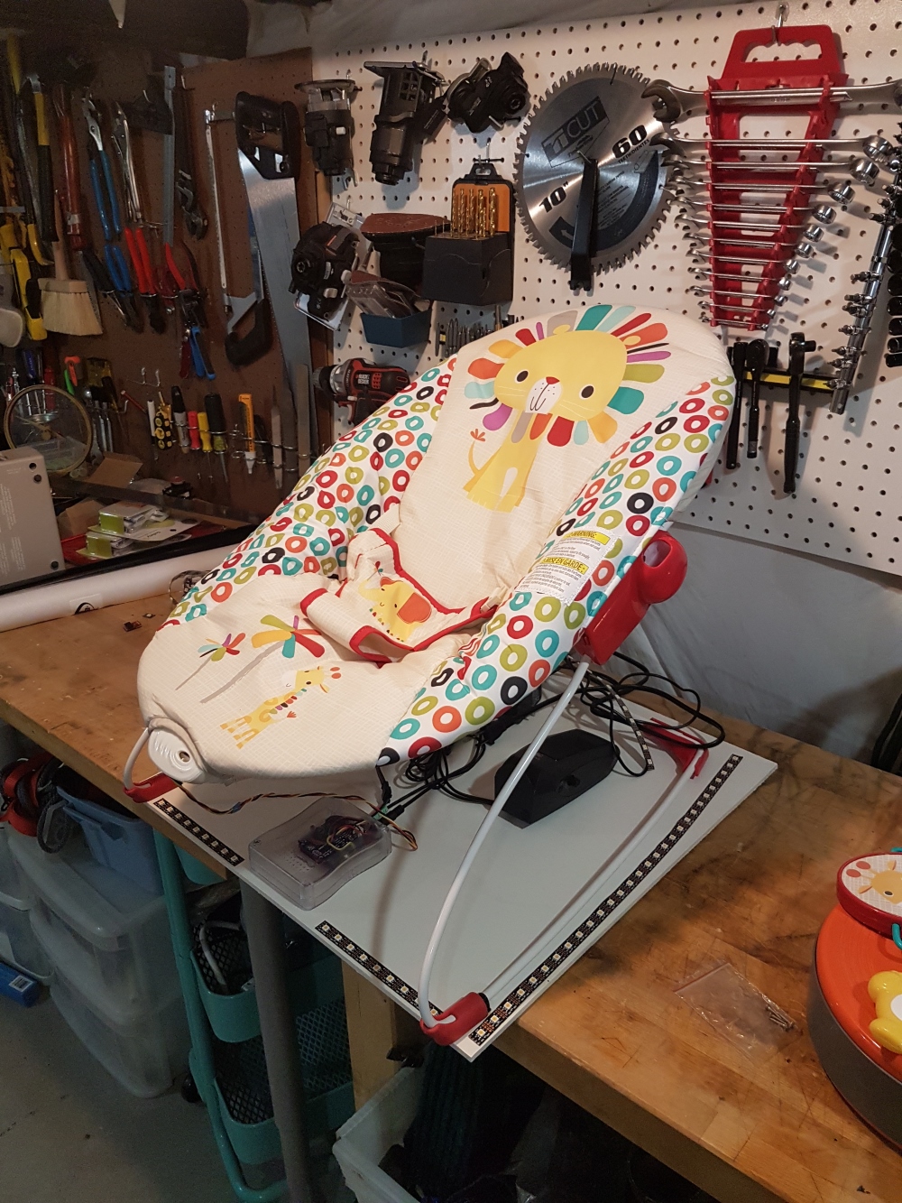
I had no idea how much money or time Ford spent but I figured I could do something similar. It might be a little too DIY... And my son might not like it at all... But I present to you The Vibe-O-Matic 3000:
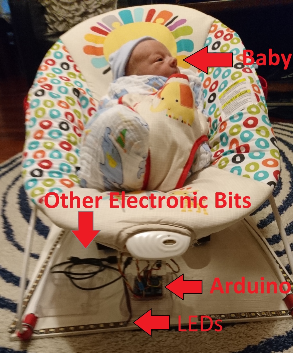
VOM3K
Ok, what’s going on here? The VOM3K is designed to replicate every aspect of riding in a car. The seat vibrates to varying degrees much the way a car will turn on, drive for a bit, stop at lights, etc. The seat lights up on the sides in a pulsating way just like a car’s headlights will light up the cabin. And the speakers play a recording of road noise recorded during a 15 minute drive.
Now for the big question. Does the baby like it, or LOVE it? Turns out the baby is just confused by it. The smart little bugger knows it’s not the car but he doesn’t quite know what it is. He doesn’t fuss or cry when he’s in it but doesn’t pass out like in the back seat of the car. Instead, he tends to stare up at me with an inquisitive look I can only interpret as “Dad, why do you keep saying the word Arduino. Am I Arduino-ing right now?!”
Required Materials
Here's the part list:
- Arduino Pro 328 - 5V/16MHz
- MP3 Player Shield
- Hook-up Wire
- Enclosure
- 5V Power Supply
- Panel Mount Barrel Jack
- MOSFET Power Control Kit
- JST Jumper 3 Wire Assembly
- Rocker Switch
- Momentary Push Button
You will also need:
- PC Speakers
- Individually Addressable Warm White LED Strip (APA102 Driver IC)
- Zip Ties
- MDF board
- Screws
- Phillips Screw Driver
Tools
You will need a soldering iron, solder, general soldering accessories, and tools to connect the project.

Hakko FX888D Soldering Station
TOL-11704You will also need:
- Hot Glue Gun w/ Hot Glue
- Comfy Baby Seat
- Hobby Motor
The Build
To build the Vibe-O-Matic, I needed three things:
- Vibration
- Sound
- Light
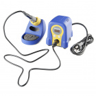
Luckily, the bouncy seat that friends gave us (thank you Victoria!) had a small vibration motor attached.

The original vibration design used a single C cell battery (approximately 1.5V) with a simple ON/OFF slide switch. I removed the power switch and battery and used the MOSFET power control kit to control the motor via the Arduino at 5V. Since the DC motor was used to vibrate the seat, it did not matter what pin was used when connecting it to the "Device" side of the n-channel MOSFET's breakout board.
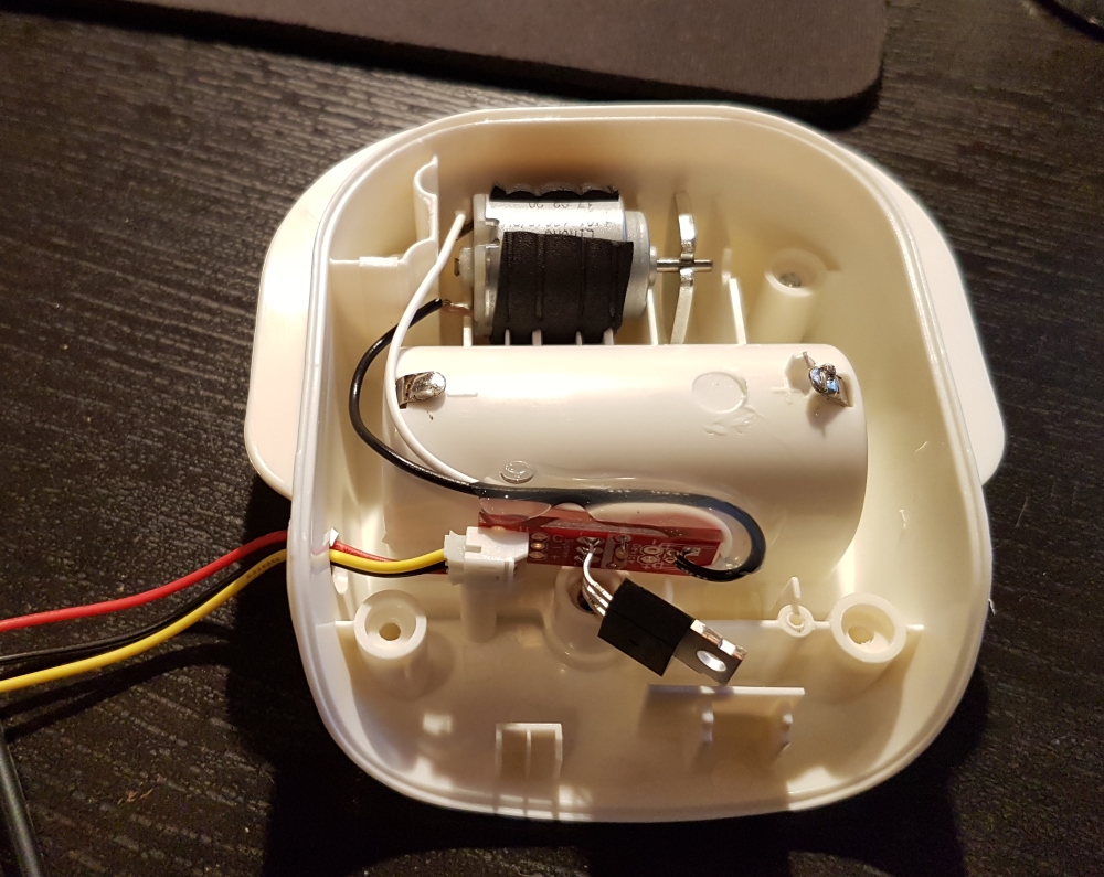
What does the motor do when run at 5V instead of the designed 1.5V? It runs a lot faster and a lot louder. Thankfully, the Arduino has PWM on a handful of pins so we are able to run the motor from 0 to 100% throttle. Therefore, if the vibration is too great (or the motor gets too warm), we can ramp down the power to an acceptable level. I ended up running the motor from about 40% to 80% power. Any higher and the boy gets even more weirded out.
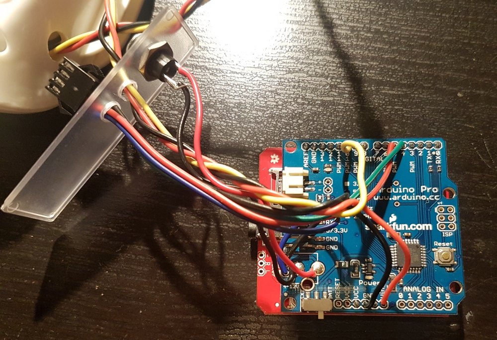
Next, I soldered an Arduino Pro to the MP3 Player Shield. Note that the Arduino is mounted above the shield. It’s not mandatory that an Arduino go below a shield. I knew I was going to need to solder a variety of additional things like switches and buttons to the Arduino. It was easier for me to mount the MP3 shield below so I could see the pins I needed to access on the Arduino. After stacking, the following wired connections were made as shown in the following table.
| Component | Arduino Pro 5V/16MHz |
|---|---|
| Panel Mount Barrel Jack's Center Pin | Barrel Jack VIN pin |
| Panel Mount Barrel Jack's Sleeve Pin | Barrel Jack GND pin |
| N-Channel MOSFET Breakout Board: "C" Pin | Pin 10 |
| N-Channel MOSFET Breakout Board: "-" Pin | GND Pin |
| N-Channel MOSFET Breakout Board: "+" Pin | VIN Pin |
| APA102 Ground: GND | "-" Pin Next to Barrel Jack Footprint |
| APA102 Data: D1 Pin | Pin 5 |
| APA102 Clock: C0 Pin | Pin 4 |
| APA102 Vcc: 5V | "+" Pin Next to Barrel Jack Footprint |
| Go!: Momentary Push Button Pin | Pin A0 |
| Go!: Momentary Push Button Pin | Pin A1 |
| Vibe Mode: Rocker Switch Normally Closed Pin | Pin A1 |
| Car Mode: Rocker Switch Normally Open Pin | Pin A2 |
I made a base board out of MDF to mount everything to. I had some extra paint around so I painted it (thinking a coat of paint would have a positive impact on my wife’s feelings about this whole endeavor). The speakers are attached with a couple of screws through the MDF into the plastic speaker housing. The enclosure and electronics were similarly secured with a couple screws.
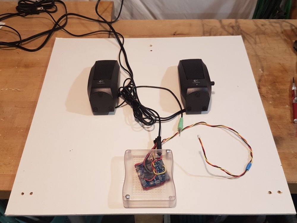
The chair was then zip tied to the MDF. The individually addressable APA102 warm white LEDs had an adhesive backing like most strips do. But like most LED strips, this backing tends to wear out after a few days so I added hot-glue to various points on the LED strip to secure it.
The APA102 LEDs are controlled with the excellent FastLED library. The ‘Cylon’ example was modified to mimic car’s headlights illuminating the cabin as they pass on the left, right, and front.

Next, I recorded a 12 minute drive through my city with the windows down. If you listen to the track you can hear where a couple large diesel trucks pass by. It’s a pretty good track although it’s hard to pick up good road noises. At one point I envisioned using a light sensor, GPS, and accelerometer to properly record the light and vibration through the drive. At that same moment my son started to scream and I decided it was better to take the SISI (screw it, ship it) approach: the LEDs trigger every 30 seconds with a random right/front/left decision and the vibration motor changes to a new, random, vibration level (40 to 80% throttle) every 60 seconds.
The Code
Note: This example assumes you are using the latest version of the Arduino IDE on your desktop. If this is your first time using Arduino, please review our tutorial on installing the Arduino IDE. If you have not previously installed an Arduino library, please check out our installation guide.
To follow along with this project, you will need to install the following libraries:
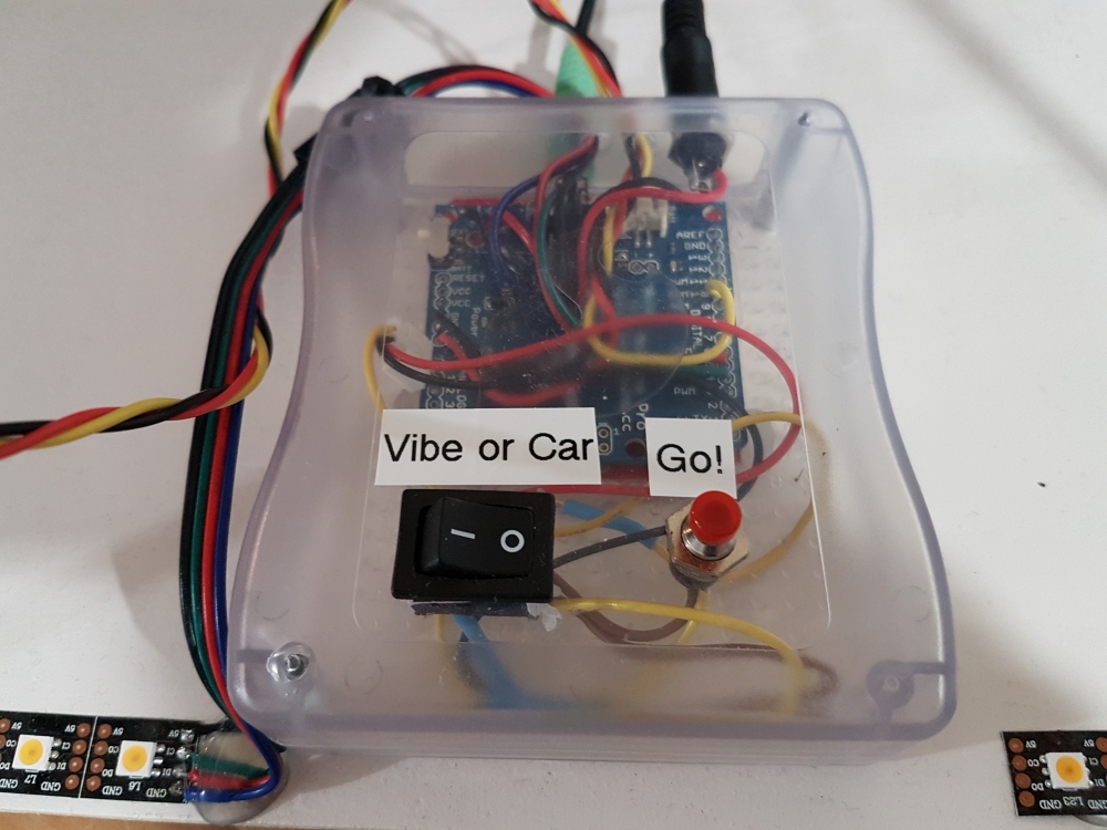
A rocker switch was used to select between Vibe (vibrate for 15 minutes, no lights or sound) and Car (the full effect). The Go! button allows the user to start or stop an action.
You can find the code for the Vibe-O-Matic 3000 here:
It looks at the state of the rocker switch and the start button to determine what to do. Once actuated the MP3 shield plays the track until completion. The LEDs and motor turn ON/OFF randomly every 30 and 60 seconds, respectively. There’s also a vibe-only mode that vibrates the chair for 15 minutes.
The Result
ReplaceMeOpen
ReplaceMeClose
In the end, Jack doesn't really like or dislike the seat. I suspect the snugness of car seat is important. I also think the vibrations in a car are at a lower frequency and a much higher amplitude than the small vibe motor can do. I hope someone can learn from my lessons and do an even better version!
Resources and Going Further
Now that you've seen how to hack a perfectly good baby gift it's time to take on the world! Check out some of these other great tutorials:
Light-Emitting Diodes (LEDs)
MP3 Player Shield Hookup Guide V15
Lumenati Hookup Guide
Thanks for reading! Please let us know if you have any questions or comments.