MP3 Player Shield Hookup Guide V15
 jimblom,
  Byron J.
 Introduction
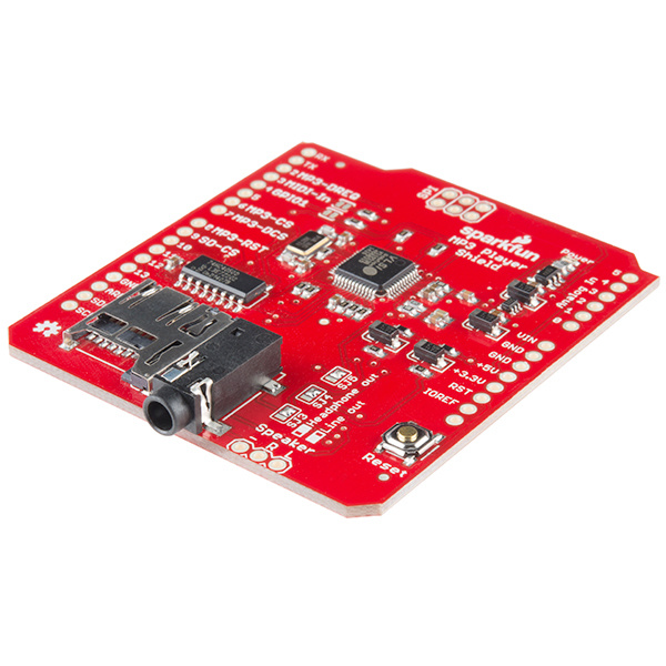
Are you looking to add some grooves to your project. Does your haunted house or Halloween costume need some sound effects embedded into it? Do you just want to be able to say you built your own MP3 player? The MP3 Player Shield is an easy way to add music or sound effects to your project.
In this tutorial we'll examine all of the ins and outs of the MP3 Player Shield. Then we'll go on to introduce some example code. Hopefully, after reading through this tutorial, you'll be inspired to make the next, great MP3 Shield Music Box or another rockin', music-playing Arduino project.
Requirements
To follow along with this tutorial you'll need the following items:
- An MP3 Player Shield, of course. The star of the show.
- µSD Card and a computer with a means to get music files onto it.
- An Arduino Uno, RedBoard, Arduino Pro or any other Arduino-compatible board.
- Headphones with a 3.5mm jack termination or an active speaker.
- Some MP3 files to groove to.
Check Your Hardware Version
This hookup guide describes output configuration features that were added to the V1.5 revision of the MP3 shield.
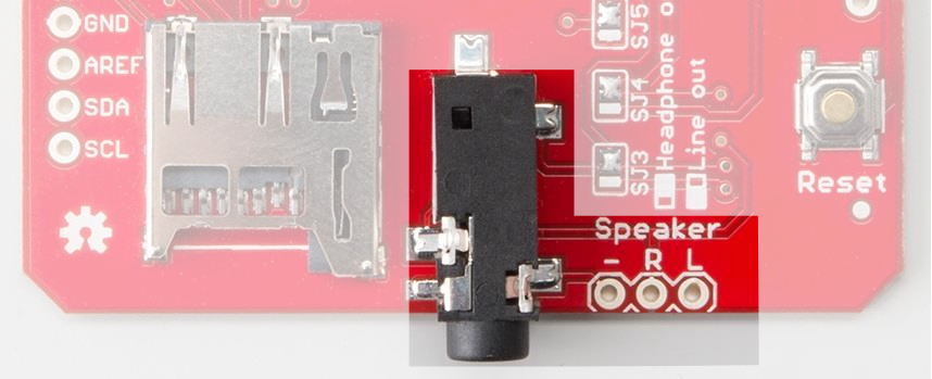
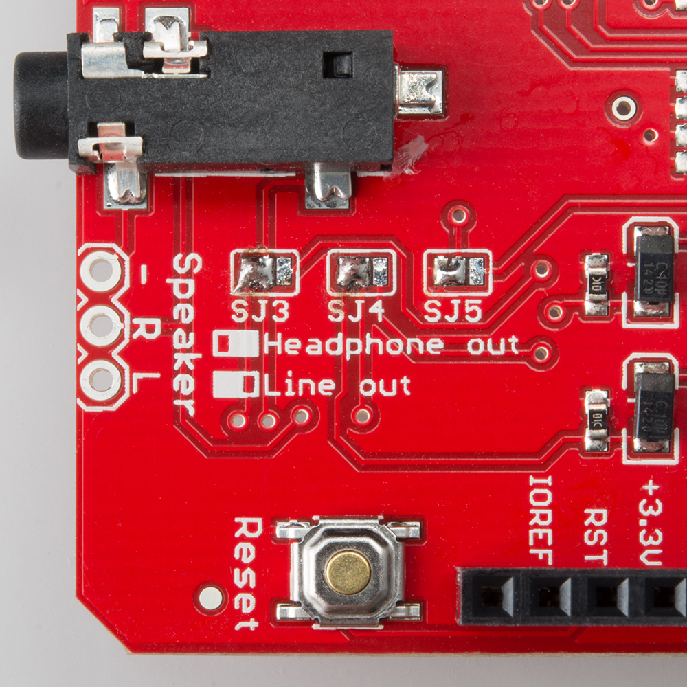
If you're not sure which version you've got, there's a version number on the bottom copper layer, underneath the headphone jack, as shown below. This guide is for boards marked "V15" (The decimal is omitted from the copper, so the version 1.5 PCB is marked 15).
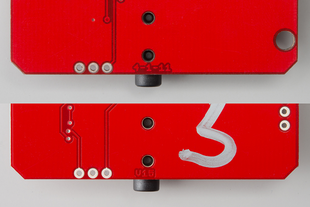
Below: Current Revision (V15)
If you have an older version of the MP3 shield, marked with the date code "4-1-11", you can find the matching hookup guide here. The most significant difference is that the V15 board adds the components to enable the AC-coupled line output.
Suggested Reading
Before launching into this tutorial, there are a few basic concepts you should be familiar with. If the subject of these tutorials sounds foreign to you, read about it before continuing on with this hookup guide.
Hardware Overview
The centerpiece of the MP3 Player Shield is a VS1053B Audio Codec IC. The VS1053B is a multitalented little chip. On top of MP3's, it can also decode Ogg Vorbis, AAC, WMA, and MIDI. (It's also capable of encoding audio, although that's outside the scope of the MP3 Shield.)
Supporting the VS1053B is a µSD card socket, which you can use to store MP3 files on. Using the Arduino SD library, it's simple to read music files off an SD card, and stream them to the VS1053B. There's additional circuitry on-board to level shift signals down to the 3.3V maximum allowable by SD cards.
Here's a quick visual overview of the important connectors and other components on the MP3 Player Shield:
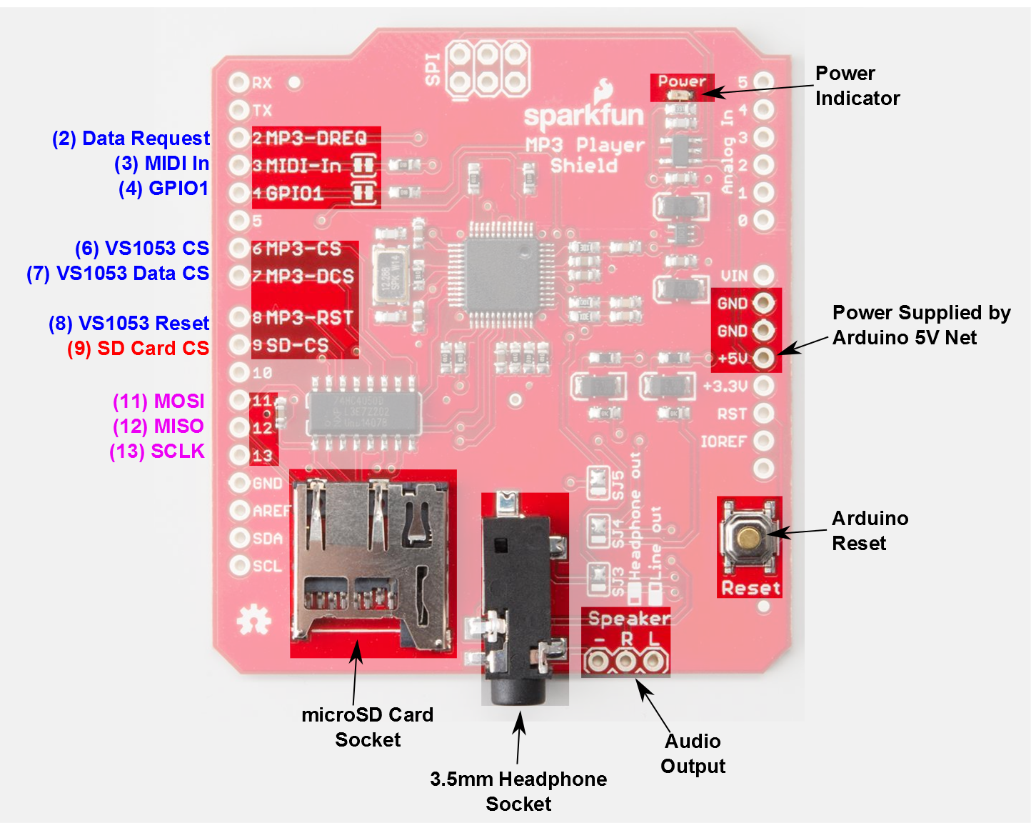
In the image above, the blue labels are pins used by the VS1053 MP3 Codec IC, the red labels are used for communication with the µSD card, and the purple-labeled pins are used by both components (yay SPI!).
Which Pins are Being Used?
The MP3 Player Shield requires exclusive use of a handful of pins. These pins can't be used to interface with other devices:
- D2 is connected to the data request output of the VS1053B. This pin is an interrupt, which tells the Arduino that the IC needs more music data.
- D6 is connected to the chip select input of the VS1053B. This active-low pin tells the chip when data is being sent to it.
- D7 is connected to the data chip select input of the VS1053B, which tells the chip when music data is being sent.
- D8 is connected to the reset input of the VS1053B.
- D9 is connected to the chip select input of the µSD card.
The Arduino's three SPI data and clock pins -- D11, D12, and D13 -- can be used to interface to other SPI components. They can't, however, be used for any purpose other than SPI.
Which Pins are Free?
Whew! The shield does use up quite a few pins, but here are the pins still available to connect to other components.
- The hardware UART pins -- RX and TX -- on pins 0 and 1
- D5 and D10 (PWM pins!)
- All analog pins (A0 through A5).
Optional Pin Jumpers
Two pins we haven't mentioned yet are D3 and D4, which are connected to the VS1053B's MIDI-In and GPIO1 pins respectively. Use of these pins is optional. They're not required for most MP3-playing functions, including the examples we'll show in this tutorial.
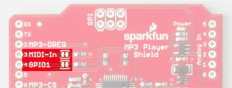
To disable either of those pins, a jumper next to their label can be cut using a hobby knife.
Getting Audio Out
The VS1053 packs a lot of features into a tiny chip. It combines an MP3 decoder, volume control, and headphone amplifier in a single IC. It's the heart of many small MP3 Players. However, because the SparkFun MP3 Player Shield finds it's way into applications beyond portable devices, the outputs need to be more flexible. In the sections below, we'll explore how to configure the output hardware, and the reasons behind that configuration.
Output Connections
The audio outputs from the board are found on the 3.5mm headphone jack, and the adjacent set of 0.1" solder pads.
The solder pads and headphone jack are wired in parallel - the same signals are present on both the pads and the jack. They are connected as follows.
| Signal Name | Jack Connection | Pad Connection |
| Left Channel | tip | "L" |
| Right Channel | ring | "R" |
| Reference (ground or GBUF) | Sleeve | "-" |
Quick Testing
The easiest way to hear the output of the MP3 Shield is to plug a set of headphones into the 3.5mm connector. The VS1053B is rated to drive 'phones with a load impedance of 16 Ω or greater - typical headphones and earbuds are frequently 32 Ω, well above the limit.
If headphones are your desired output method, you can plug them in and skip ahead to the next section. But if you want to interface with other devices, such as a connection to your computer, an external amplifier, or larger speakers, keep reading.
Output Circuit Details
The VS1053B is designed for battery-powered applications that drive headphones. In particular, the headphone amplifier circuitry is optimized for this scenario - which makes other use cases a little harder. It's a complex enough topic that VLSI published an application note to illustrate proper interconnection.
First, let's take a closer look at how the output is tailored to driving headphones.
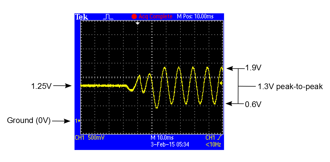
Specifically, the signals coming from the VS1053 are DC coupled. This means that the alternating-current (AC) audio signals are riding on top of a 1.25 V DC offset. The datasheet specifies that the output can swing about 2 V peak-to-peak, which results in output signals that swing between 0.25V and 2.25 V.
There are two tricky things that allow this to work. First, headphones are self-contained - they don't have any other connections to ground.
The other thing is that the VS1053B provides a special DC reference voltage output. The chip generates the "GBUF" output, held at 1.25 VDC, to be tied to the sleeve of the headphone connection. When the player is quiet, the output and the reference are both 1.25 V, so no current flows. When signal is present, it's the potential difference between the output and GBUF that makes current flow, making the drivers in the headphones move, creating sound.
In spite of the "G" in it's name, GBUF is not ground - in the pin descriptions, the datasheet specifically warns us "Common buffer for headphones, do NOT connect to ground!"
Where This Breaks Down
While this works fine for headphones, things get more complicated when we want to tie the output to other devices, especially when they have ground connections of their own. The datasheet describes the following situation:
- The player is powered via a USB connection to a PC - as we commonly do with Arduino boards. The USB jack is grounded inside the PC.
- The output from the player is plugged into the PC line input jack, using a 3.5mm cable.
As described above, the sleeve of the headphone output is the GBUF signal, with a 1.25V DC offset on it - but the sleeve of the PC line input is grounded, at 0 V.
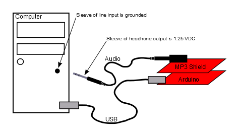
Plugging the two of them together causes a short circuit, and can potentially damage the circuitry on either end of the connection!
Engage AC-Coupling
To solve this, we need to get rid of the DC voltage present on the MP3 player shield outputs. Getting rid of the DC voltage is known as AC-coupling (sometimes also called DC blocking). The AC portion of the output (the audio waveform itself) is transferred (or coupled) to the other device, but the DC offset is removed. The VS1053B application note makes several recommendations for AC-coupling the output - we implemented the circuit shown in Figure 8.
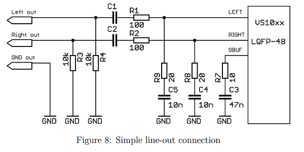
The AC-coupling circuit is enabled with solder jumpers SJ3, SJ4 and SJ5. By reconfiguring those jumpers, we can convert the outputs from a DC-coupled headphone out to an AC-coupled line output.
- SJ3 and SJ4 add 10 µF capacitors in line with the L and R outputs. The 1.25 V offset doesn't cross the caps, effectively recentering the waveforms about 0V
- SJ5 changes the sleeve and "-" terminal to connect to ground, rather than GBUF, avoiding the short circuit illustrated above
The jumpers all work together - they should all be set in the same direction.
To change the jumpers, first heat up and remove the default blobs using a solder sucker or solder wick. Then flow fresh solder onto the other pair of pads. It can be useful to verify your work with a magnifying glass, or a continuity tester.
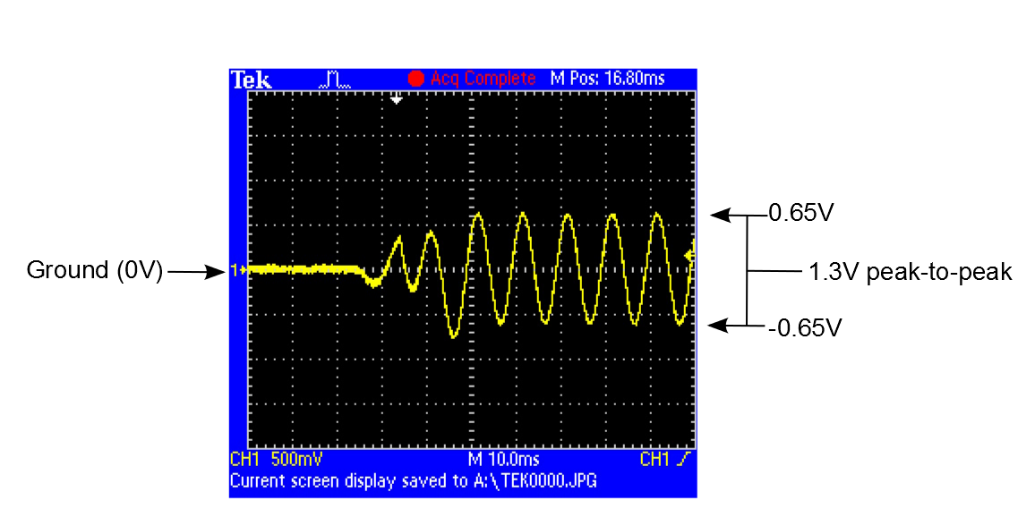
With the jumpers swapped, the output waveforms are re-oriented around ground.
So why not just have the AC-coupling circuitry enabled all the time? There is one primary reason: the added resistors in series with the outputs make headphones much quieter than the DC-coupled configuration. This isn't an issue for line inputs, which are frequently 10kΩ or higher, but it becomes a significant voltage divider when driving low imepdance headphones. Louder is better, right?
External Speakers
If you want to make the MP3 Player Shield audible to others, you'll want to add external speakers. While you can simply plug speakers into the headphone output, the onboard circuit isn't sufficiently powerful to drive them - they'll be extremely quiet.
One simple solution that pops up here at SparkFun HQ is to simply plug the player into a set of self-powered multimedia PC speakers.
If you're looking for a DIY solution to driving speakers, consider using our Mono Audio Amp Breakout or Stereo Amplifier Kit.
Output Configuration Summarized
| To Connect | Set SJ3, SJ4, SJ5 | Additional Hardware |
| Headphones | For headphones (To the Right) | - |
| External active devices (PC, stereo reciever, powered speakers, etc) | For line out (To the Left) | - |
| Passive Speakers | For line out (To the Left) | Audio Amplifier |
Assembly & Preparation
Before we get to uploading code and streaming some tunes, there are some a few preparation steps to take care of first. You'll need to solder something to the shield, and prepare a µSD card.
Adding Headers
To get started with the shield, you'll need to solder on some headers. If you're looking to keep the shields stackable, our R3 stackable header set might be the best option. Otherwise, straight male headers work as well.
Check out our shield assembly guide for more help in adding headers to your shield.
MP3 File and µSD Card Setup
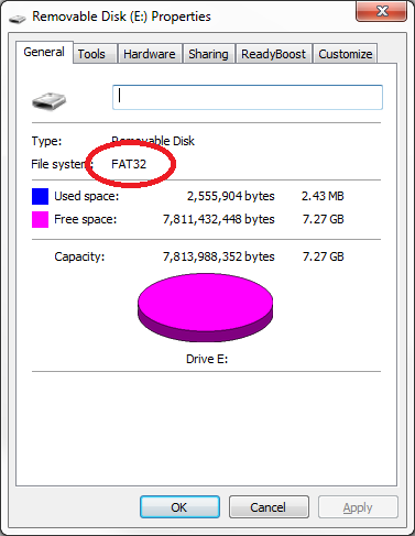
In this phase of the hookup, you may also want to start preparing your µSD card. First, make sure it's formatted correctly. The SDFat Arduino library we'll be using only supports cards formatted for FAT16 or FAT32. Your card is probably already formatted to one of these standards, but it doesn't hurt to double check.
You may also want to prepare your music files. The VS1053B is capable of playing MP3, AAC, WMA, MIDI, and Ogg Vorbis audio files. The VS1053B supports a variety of samplerates and bitrates for each file type. Check out the datasheet (beginning in section 8 -- page 26), to make sure your audio files are supported. MP3's, for example, are supported at up to a 320 kbps bitrate and a 48 kHz samplerate.
Finally, before loading the audio files onto your SD card, you'll need to modify their names. The SDFat library only supports "8.3" file names -- that's eight characters before the '.' and three characters after (e.g. "track001.mp3"). Further, some of the example code we'll be using later on requires that the audio files be named using special conventions. In the MP3 trigger example the files will need to be named "track001.mp3", "track002.mp3", etc.
Using the SFEMP3Shield Library
The SFEMP3Shield Arduino library -- written collaboratively by Bill Porter, Michael Flaga, ddz, and Wade Brainerd -- is an AMAZING resource for the MP3 Player Shield. Combined with the equally awesome SdFat library, SFEMP3Shield greatly simplifies the task of interfacing with the VS1053 and using the MP3 Player Shield.
We recommend using the SFEMP3Shield library with this shield. On this page we'll go over how to install and use the library. On the next page, we'll make a fun example sketch using it.
Install the SFEMP3Shield Library
To download the latest version of the SFEMP3Shield, click the "Download ZIP" link on the library's GitHub page. You should also be able to grab it directly from here.
This GitHub repo already includes a copy of the SdFat library, so you're covered there.
The "Sparkfun-MP3-Player-Shield-Arduino-Library-master" folder you extract should have a handful of folders within. The "SFEMP3Shield" and "SdFat" folders in particular need to be installed as Arduino libraries. For help installing the library, check out our Installing an Arduino Library tutorial. You'll need to place those two folders within your Arduino sketchbook (by default in your home/Arduino folder). Your file structure should look something like this once installed:
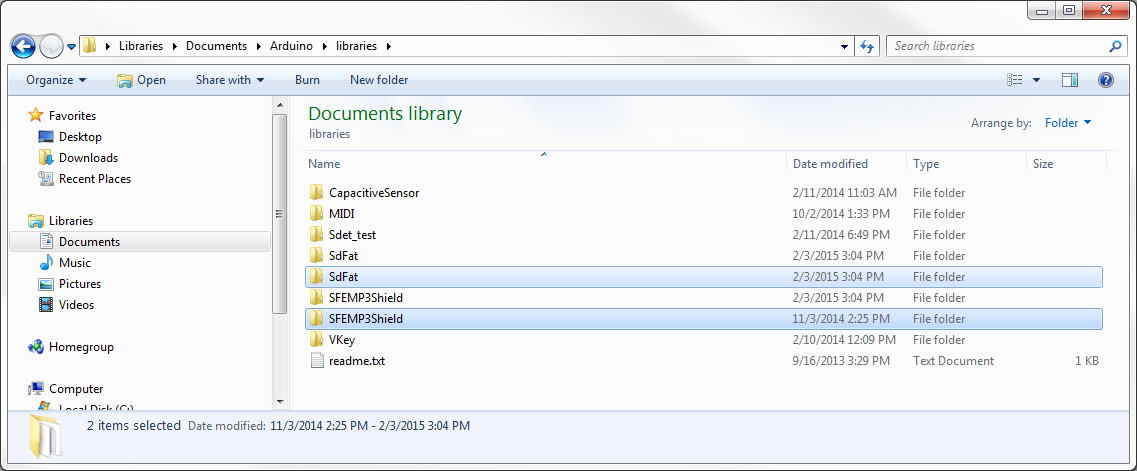
Now restart Arduino (if it was open), and check under the "Sketch" > "Import Library" menu to make sure "SFEMP3Library" and "SdFat" are both listed there.
Upload an Example Sketch
The SFEMP3Shield library includes a few fun example sketches that show off all of its awesome abilities. To begin, try loading up the "FilePlayer" example, by going to "File" > "Examples" > "SFEMP3Shield" > "Examples" > "FilePlayer".
Make sure the MP3 Player Shield is sitting comfortably on top of your Arduino, and upload away!
Once uploaded, open up the Serial Monitor and set the baud rate to 115200 bps. In our expreience, this sketch works best with the serial monitor in the Arduino IDE. Once the sketch initializes, it should present you with a navigable menu:
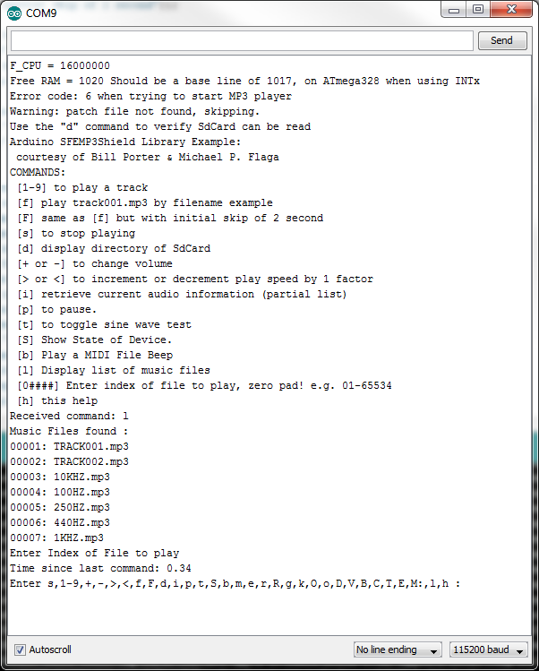
Hopefully, towards the bottom of the menu, you'll see a list of MP3 files that the sketch found on your SD card. Try sending a 3-digit number with leading zeros (e.g. 001, 003, etc.) to make one of the listed files start playing. Are you grooving now?
If it's too quiet, try turning up the volume using the '+' command, or go down with '-'. There are all sorts of other fun options to try out too.
Helpful SFEMP3Shield Library Documents
If you're looking for help using the SFEMP3Shield, begin by checking out the main page of their support site. There's some good troubleshooting information there.
To dig into the code, you can check out their GitHub repository. There's also a helpful SFEMP3Shield Class Reference guide, which lists all of the functions made available by the library.
On the next page, we'll make an example sketch using the MP3ShieldLibrary to show off some of its more fundamental functions.
Example Sketch: MP3 Trigger
Whether it's red or purple, everyone loves a good MP3 trigger. Where a simple button or switch is all it takes to trigger a song or sound effect. Let's use the MP3 Player Shield library to make an MP3 trigger that can rival the big boys.
This is a simple example, which shows how to play and stop tracks using the SFEMP3Shield library. Up to nine tracks can be triggered by the shield, using pins 0, 1, 5, 10, and A0-A4. A5 can be used to stop a currently playing track.
Step 1: Set up the SD Card
You'll need to rename your MP3 files before plugging the µSD card into your shield. Each of the nine tracks needs to be specifically named from "track001.mp3" to "track009.mp3".
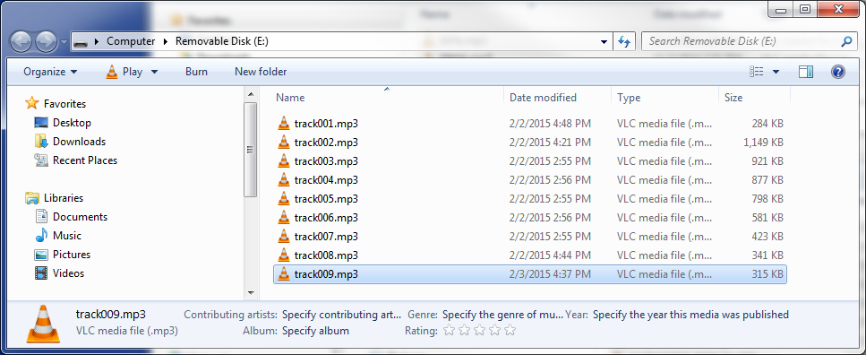
The first trigger -- D0 -- will play an MP3 named "track001.mp3", the second trigger -- D1 -- will play "track002.mp3", and so on up to A4 which will play "track009.mp3".
Step 2: Set up the Hardware
Of course, the shield does most of the hardware set up for you. Aside from sticking the shield on your Arduino, you'll need to find something to trigger the pins. You could use a switch, of which there are tons of options, or you could just us a simple jumper wire to ground one of the trigger pins.
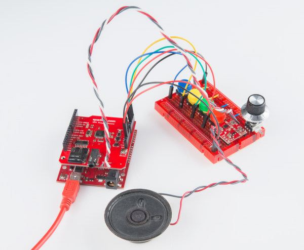
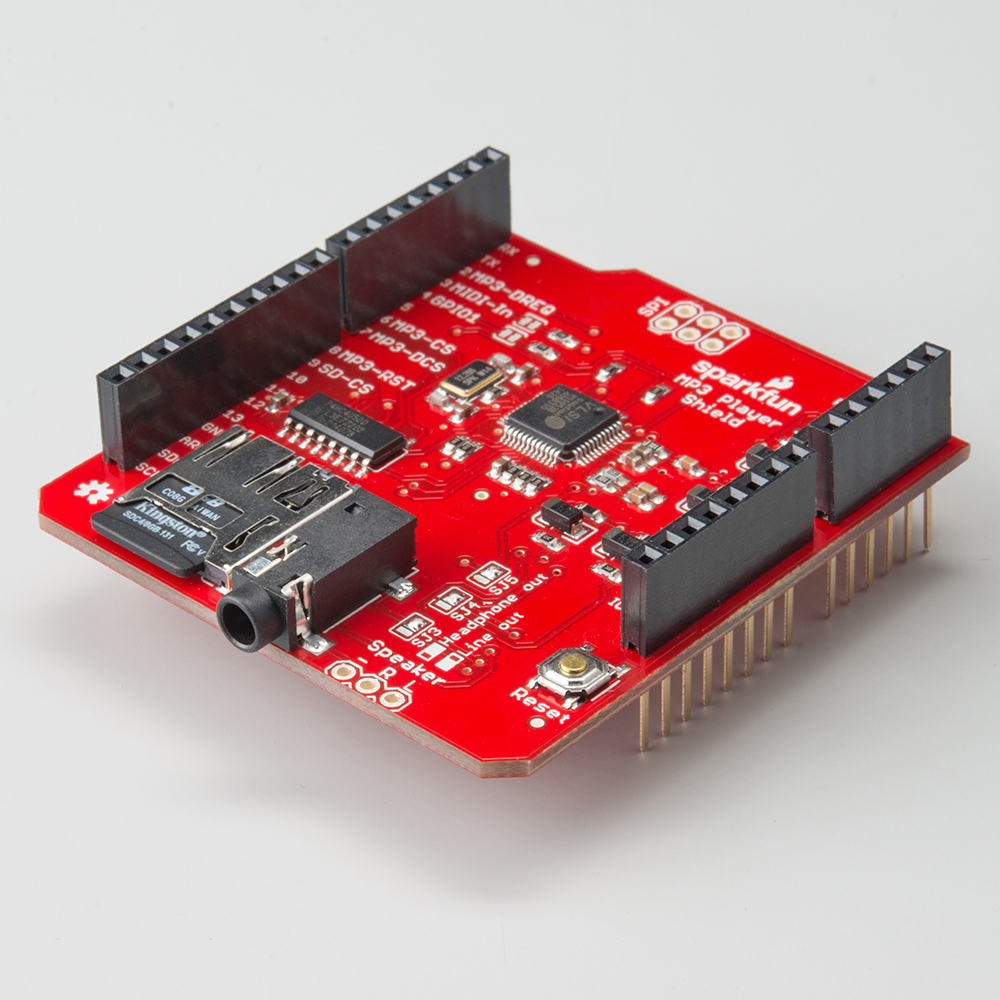
The photo above shows a prior revision of the MP3 Player Shield. The circuit for wiring up the MP3 Trigger example is identical.
Once you have configured the output, you can either plug headphones into the on-board jack to listen, or, if you want to get fancy with it, use the three broken out "Speaker" pins. Here's our setup with a combination of MonoAmp Breakout and 8 Ω Speaker:
Step 3: Load Up the Code
Here's our MP3 Shield trigger sketch. Copy/paste from below, or download it here:
language:c
/*
  MP3 Shield Trigger
  by: Jim Lindblom
      SparkFun Electronics
  date: September 23, 2013

  This is an example MP3 trigger sketch for the SparkFun MP3 Shield.
  Pins 0, 1, 5, 10, A0, A1, A2, A3, and A4 are setup to trigger tracks
  "track001.mp3", "track002.mp3", etc. on an SD card loaded into
  the shield. Whenever any of those pins are shorted to ground,
  their respective track will start playing.

  When a new pin is triggered, any track currently playing will
  stop, and the new one will start.

  A5 is setup to globally STOP playing a track when triggered.

  If you need more triggers, the shield's jumpers on pins 3 and 4
  (MIDI-IN and GPIO1) can be cut open and used as additional
  trigger pins. Also, because pins 0 and 1 are used as triggers
  Serial is not available for debugging. Disable those as
  triggers if you want to use serial.

  Much of this code was grabbed from the FilePlayer example
  included with the SFEMP3Shield library. Major thanks to Bill
  Porter and Michael Flaga, again, for this amazing library!
*/

#include <SPI.h>           // SPI library
#include <SdFat.h>         // SDFat Library
//#include <SdFatUtil.h>     // SDFat Util Library
#include <SFEMP3Shield.h>  // Mp3 Shield Library

SdFat sd; // Create object to handle SD functions

SFEMP3Shield MP3player; // Create Mp3 library object
// These variables are used in the MP3 initialization to set up
// some stereo options:
const uint8_t volume = 0; // MP3 Player volume 0=max, 255=lowest (off)
const uint16_t monoMode = 1;  // Mono setting 0=off, 3=max

/* Pin setup */
#define TRIGGER_COUNT 9
int triggerPins[TRIGGER_COUNT] = {0, 1, 5, 10, A0, A1, A2, A3, A4};
int stopPin = A5; // This pin triggers a track stop.
int lastTrigger = 0; // This variable keeps track of which tune is playing

void setup()
{
  /* Set up all trigger pins as inputs, with pull-ups activated: */
  for (int i=0; i<TRIGGER_COUNT; i++)
  {
    pinMode(triggerPins[i], INPUT_PULLUP);
  }
  pinMode(stopPin, INPUT_PULLUP);

  initSD();  // Initialize the SD card
  initMP3Player(); // Initialize the MP3 Shield
}

// All the loop does is continuously step through the trigger
//  pins to see if one is pulled low. If it is, it'll stop any
//  currently playing track, and start playing a new one.
void loop()
{
  for (int i=0; i<TRIGGER_COUNT; i++)
  {
    if ((digitalRead(triggerPins[i]) == LOW) && ((i+1) != lastTrigger))
    {
      lastTrigger = i+1; // Update lastTrigger variable to current trigger
      /* If another track is playing, stop it: */
      if (MP3player.isPlaying())
        MP3player.stopTrack();

      /* Use the playTrack function to play a numbered track: */
      uint8_t result = MP3player.playTrack(lastTrigger);
      // An alternative here would be to use the
      //  playMP3(fileName) function, as long as you mapped
      //  the file names to trigger pins.

      if (result == 0)  // playTrack() returns 0 on success
      {
        // Success
      }
      else // Otherwise there's an error, check the code
      {
        // Print error code somehow, someway
      }
    }
  }
  // After looping through and checking trigger pins, check to
  //  see if the stopPin (A5) is triggered.
  if (digitalRead(stopPin) == LOW)
  {
    lastTrigger = 0; // Reset lastTrigger
    // If another track is playing, stop it.
    if (MP3player.isPlaying())
      MP3player.stopTrack();
  }
}

// initSD() initializes the SD card and checks for an error.
void initSD()
{
  //Initialize the SdCard.
  if(!sd.begin(SD_SEL, SPI_HALF_SPEED))
    sd.initErrorHalt();
  if(!sd.chdir("/"))
    sd.errorHalt("sd.chdir");
}

// initMP3Player() sets up all of the initialization for the
// MP3 Player Shield. It runs the begin() function, checks
// for errors, applies a patch if found, and sets the volume/
// stero mode.
void initMP3Player()
{
  uint8_t result = MP3player.begin(); // init the mp3 player shield
  if(result != 0) // check result, see readme for error codes.
  {
    // Error checking can go here!
  }
  MP3player.setVolume(volume, volume);
  MP3player.setMonoMode(monoMode);
}
Check the comments in the code for a step-by-step walkthrough. This example shows just how easy it is to use the MP3 Player Shield (with a lot of thanks to Bill Porter and Michael Flaga for their library). Call the MP3player.playTrack() function to start a song, and use MP3player.stopTrack() call to stop it.
Step 4: Trigger Some Tunes
With the sketch loaded up, all you have to do is ground one of the trigger pins (0, 1, 5, 10, A0, A1, A2, A3, A4). When a new trigger pin is grounded, any currently playing song will stop and the MP3 file it relates to will start playing. If you want to stop a track, briefly connect A5 to ground.
You can connect any of these trigger pins up to all kinds of buttons or switches, or just use a strand of wire to momentarily short them to ground.
Resources and Going Further
The tutorial's over, but there are still plenty of resources to help you get the most out of your MP3 Player Shield:
- MP3 Player Shield Schematic
- MP3 Player Shield Eagle Files
- VS1053B Datasheet
- VLSI VS1053B Product Page
- Bill Porter's SFEMP3Shield Library GitHub Repository
- SFEMP3Shield Library Support Page
- GitHub Repo
Going Further
Your MP3 Player Shield is all hooked up! What project are you going to stick it into? If you're looking for some inspiration, check out some of these tutorials:
- Getting Started with the LilyPad MP3 Player -- The LilyPad MP3 Player is a unique combination of LilyPad, Arduino, and the MP3 Player Shield. You can use it to create all kinds of noisy projects, from MP3 hoodies to talking teddy bears.
- My Drunk Kitchen Apron -- A fun "talking" apron that uses the LilyPad MP3 trigger.
- MP3 Player Shield Music Box -- Have you ever wanted to create a Doctor Who themed music box? This tutorial will show you how!
- RN-52 Bluetooth Hookup Guide -- Switching gears here a bit...if you want to free your music from those constricting cables, check out the RN-52 bluetooth audio module.