Using the BlueSMiRF
Hardware Hookup
Assembly
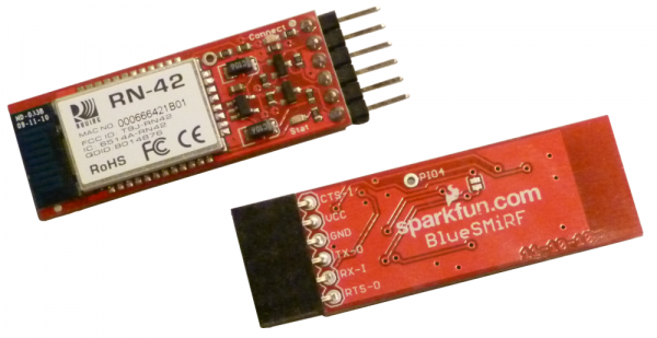
Happily, most of the assembly on these modules is done for you; you don't need to learn how to solder SMD components just yet. However, before you can begin using these Bluetooth modules, you'll need to solder something into the six plated-through-holes to form a solid electrical connection.
What you solder into the holes depends mostly on what you're going to connect the device to. If you've got a Bluetooth Mate, and want to connect it directly to an Arduino Pro, you may want to throw a right-angle female header on there. Another good option, which makes the board breadboard-compatible, is male-headers. A third, ever-reliable option is to solder wires directly to the holes.
Connecting Everything Together
We need to connect the Bluetooth modems to devices that can send and receive serial signals. These are TTL-level serial signals, make sure you don't confuse that with RS-232! Voltages should be between 3.3V and 5V. There are loads of options here, for this tutorial we'll use an Arduino.
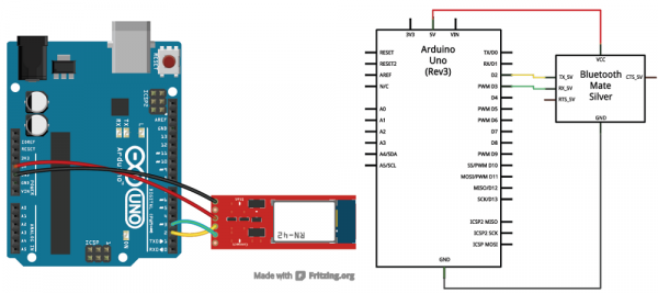
Instead of connecting the Bluetooth modem to the Arduino's lone hardware UART, we'll use SoftwareSerial and connect the modem's RX and TX pins to any of the Arduino's free digital pins. This will help to avoid bus contention and will make sure the Bluetooth modem doesn't receive any spurious data during a sketch upload. Here's the connections we'll make for the example code later in this tutorial:
TX-O is connected to D2 of the Arduino, RX-I is connected to D3, GND goes to GND, and VCC goes to 5V. The CTS-I and RTS-O pins are left floating. The TX-O and RX-I pins could really be connected to any digital pin (besides 0 and 1), so if you need 2 and 3 for something else, feel free to move those around.
Half of the hardware hookup is done. We still need to create a wireless connection to another Bluetooth device. Before we can delve further into that, though, we need to understand more about the Bluetooth modem's firmware.

