Using OpenSegment
 Nate
Nate 
Basics
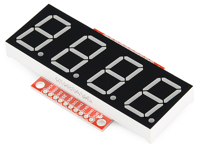
OpenSegment is a simple to use 7-segment display. It has the ability to communicate over serial, I2C, SPI, as well as analog and counter modes. It is super easy to use if you just need to display a number but have a lot of features including setting brightness levels and individual segment control built in.
The OpenSegment is the big brother to the Serial7Segment by Jim Lindblom. Both products use the same firmware but have different hardware layouts. Therefor, you can rely heavily on Jim’s datasheet for Serial7Segment and all the example code located here.
Suggested Reading
Things you may need to know before working with one of these boards:
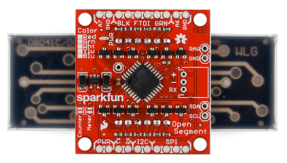
Hardware Info
OpenSegment can be powered from 4V (less bright) to 12V, but we recommend 5 to 6V. The default communication is 9600bps over serial.
Note: At any time the device can be reset to factory defaults (9600bps) by tying the RX pin to GND and powering up the device. See the Factory Reset section for more information.
The onboard regulator will regulate down to 5V. The regulator will protect against shorts, reverse power, over current, and overheating. Powering the board with more than 7V is ok, but the regulator will begin to dissipate the extra power by heating up and--depending on the brightness setting and input voltage--may cause the board to flicker.
The OpenSegment has an ATmega328 running a modified Optiboot bootloader. It’s basically a little Arduino running at 8MHz. You can reprogram the board using a standard serial connection. We always have an FTDI basic handy to make code changes, but you shouldn’t ever have to reprogram the display unless you really want to tweak the code.
Serial Communication
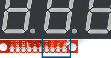
The easiest way to control OpenSegment is over serial. You need only 3 pins: PWR, GND and RX. The RX pin on OpenSegment should be connected to the TX pin of your microcontroller.
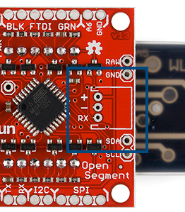
The easiest way to physically connect to OpenSegment is through a 3-pin JST connector.
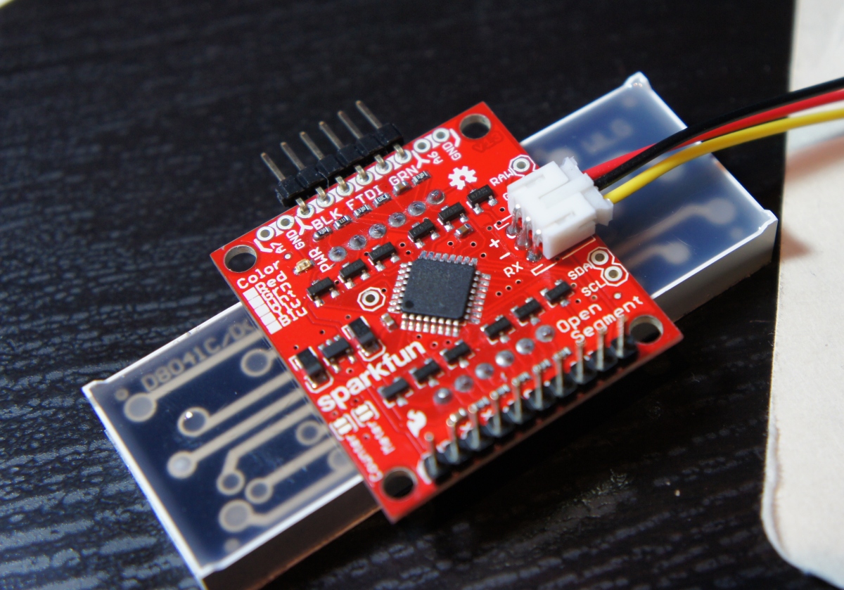
Solder the JST onto the backpack, plug the JST cable in, and then plug the red wire to 5V to 7V, black wire to GND, and yellow wire to the TX pin of your development board.
Serial Example
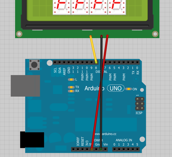
Using an OpenSegment display with Arduino is very straightforward. Power the display from the 5V pin, GND, and connect the RX pin of the display to pin 8 on the Arduino.
Here is an example to get you started immediately.
Note: This example assumes you are using the latest version of the Arduino IDE on your desktop. If this is your first time using Arduino, please review our tutorial on installing the Arduino IDE.
If you have not previously installed an Arduino library, please check out our installation guide.language:c
/*
9-23-2012
Spark Fun Electronics
Nathan Seidle
This code is public domain but you buy me a beer if you use this and we meet someday (Beerware license).
Serial7Segment is an open source seven segment display.
This is example code that shows how to display basic numbers on the display.
Note: This code expects the display to be listening at 9600bps. If your display is not at 9600bps, you can
do a software or hardware reset. See the Wiki for more info:
http://github.com/sparkfun/Serial7SegmentDisplay/wiki/Special-Commands#wiki-baud
To get this code to work, attached an Serial7Segment to an Arduino Uno using the following pins:
Pin 8 on Uno (software serial TX) to RX on Serial7Segment
VIN to PWR
GND to GND
*/
#include <SoftwareSerial.h>
SoftwareSerial Serial7Segment(7, 8); //RX pin, TX pin
int cycles = 0;
void setup() {
Serial.begin(9600);
Serial.println("OpenSegment Example Code");
Serial7Segment.begin(9600); //Talk to the Serial7Segment at 9600 bps
Serial7Segment.write('v'); //Reset the display - this forces the cursor to return to the beginning of the display
}
void loop()
{
cycles++; //Counting cycles! Yay!
Serial.print("Cycle: ");
Serial.println(cycles);
char tempString[10]; //Used for sprintf
sprintf(tempString, "%4d", cycles); //Convert deciSecond into a string that is right adjusted
//sprintf(tempString, "%d", cycles); //Convert deciSecond into a string that is left adjusted (requires digit 1 command)
//sprintf(tempString, "%04d", cycles); //Convert deciSecond into a string with leading zeros
//sprintf(tempString, "%4X", cycles); //Count in HEX, right adjusted
//int negativeCycles = cycles * -1;
//sprintf(tempString, "%4d", negativeCycles); //Shows a negative sign infront of right adjusted number
//Note: This method works well as long as your number is less than or equal to 4 digits.
//14422 will cause the display to wrap (5 digits)
//-5766 will cause the display to wrap (5 digits)
//To fix this, send a 'v' character or look at how to control the digit placement
//https://github.com/sparkfun/Serial7SegmentDisplay/wiki/Basic-Usage#wiki-cursor
Serial7Segment.print(tempString); //Send serial string out the soft serial port to the S7S
delay(10);
}
Load the above example code onto your Arduino, and watch the display count up!
You can find many more examples here on GitHub. There are sketches to show you:
- Basic counting
- Controlling the colon and dots on a display
- Changing the mode
- Fun Predator mode
- Changing the baud rate
- Doing a software serial reset
I2C/SPI Communication
If you need to control lots of displays at the same time, OpenSegment has the ability to communicate over I2C and SPI.
I2C Communication
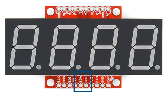
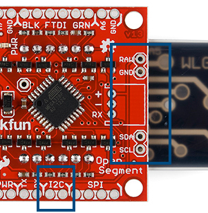
The I2C pins are labeled on the edge of the backpack and on the sides to make it easier to chain many displays together.
The default 7-bit I2C address is 113 in base10 or 0x71 in HEX or 01110001 in binary.
OpenSegment supports standard 100kHz as well as Fast 400kHz I2C speeds. Use the following code to enable Fast I2C within Arduino:
Wire.begin(); //Join the bus as controller.
//By default .begin() will set I2C SCL to Standard Speed mode of 100kHz
Wire.setClock(400000); //Optional - set I2C SCL to High Speed Mode of 400kHz
Checkout the I2C examples on GitHub for good code to start from.
You can find many more I2C examples here on GitHub. There are sketches to show you:
SPI Communication
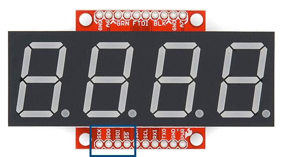
SPI communication requires 6 pins: SDO, SDI, SCK, CS, PWR, and GND. We may add a feature in the future, but for now OpenSegment does not pass data out of the SDO (serial data out) pin and can be left disconnected. If you’re hooking multiple OpenSegments together on the same SPI bus, the CS pin on each display must be connected to a different GPIO on your microcontroller.
You can find many more SPI examples here on GitHub. There are sketches to show you:
Counter/Analog Modes
OpenSegment has three modes:
- Data mode (where you send commands and data over Serial/SPI/I2C)
- Counter mode (count up/down based on SDI/SDO)
- Analog meter mode (display analog voltages on A6/A7)
We’ve covered the basic data mode; let’s cover the other two modes.
To control the mode of the display, send the command 0x82 over serial followed by:
- 0 for data mode
- 1 for analog meter mode
- 2 for counter mode
An example of how to do this over serial is available here.
You do not need to solder the jumper to control the mode. Please read the solder jumper section below for more information.
Counter Mode
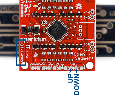
When the display is in Counter mode, the display will increase by one every time the SDI pin (i is for increase!) is pulled low and will decrease by one every time the SDO pin is pulled low. This mode was created to monitor and count the number of times a button is pressed or a reed switch is closed. The display must be power cycled to reset the count.
Analog Meter Mode
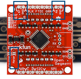
When the display is in Analog mode the instantaneous analog voltage on pins A7 and A6 will be shown on the display with 1/10th volt resolution (0.0V to 5.0V).
The voltage on A6 is displayed on the left and A7 is displayed on the right. This mode was created to monitor basic voltages (0 to 5V) without the need of a multimeter.
Solder Jumpers
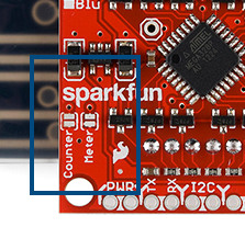
You can use OpenSegment as a counter and as an analog meter without any software configuration. By closing a solder jumper on the back of the display OpenSegment will enter one of two modes: Counter or Analog Meter mode.
Closing a solder jumper will override any software settings and will force the display into that mode after power up. If both jumpers are closed the display will startup in Counter mode.
Factory Reset
Have you forgotten what baud rate the device has been configured to? Don’t worry! The device can be reset to factory defaults by tying the RX pin to GND and then powering up the device.
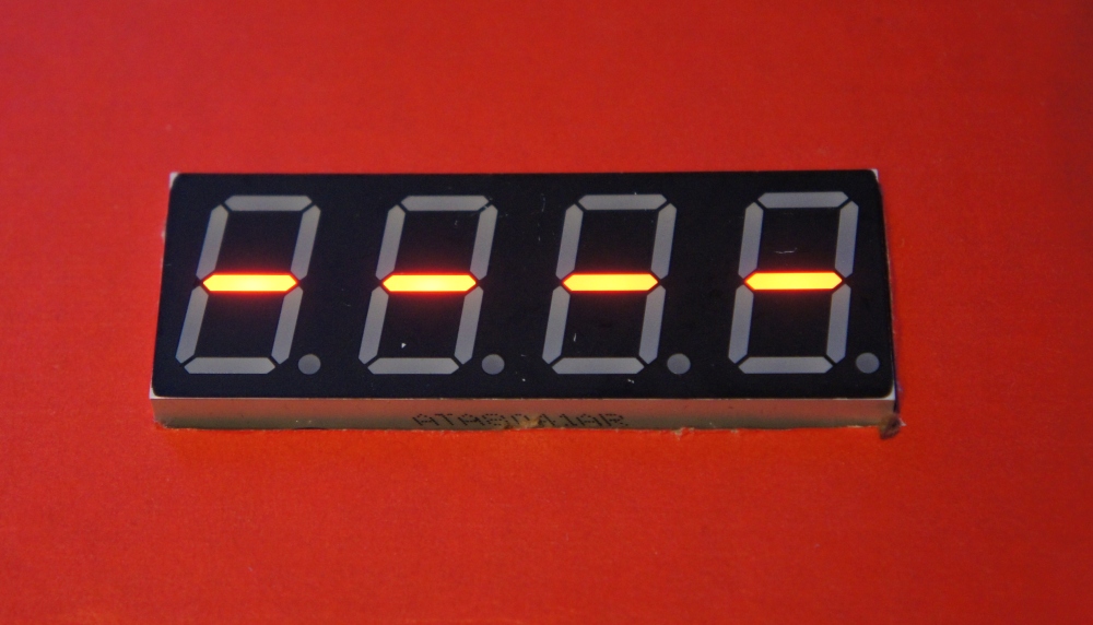
Once powered up you will see alternating - (dashes) and _ (underscores) for 1 second.

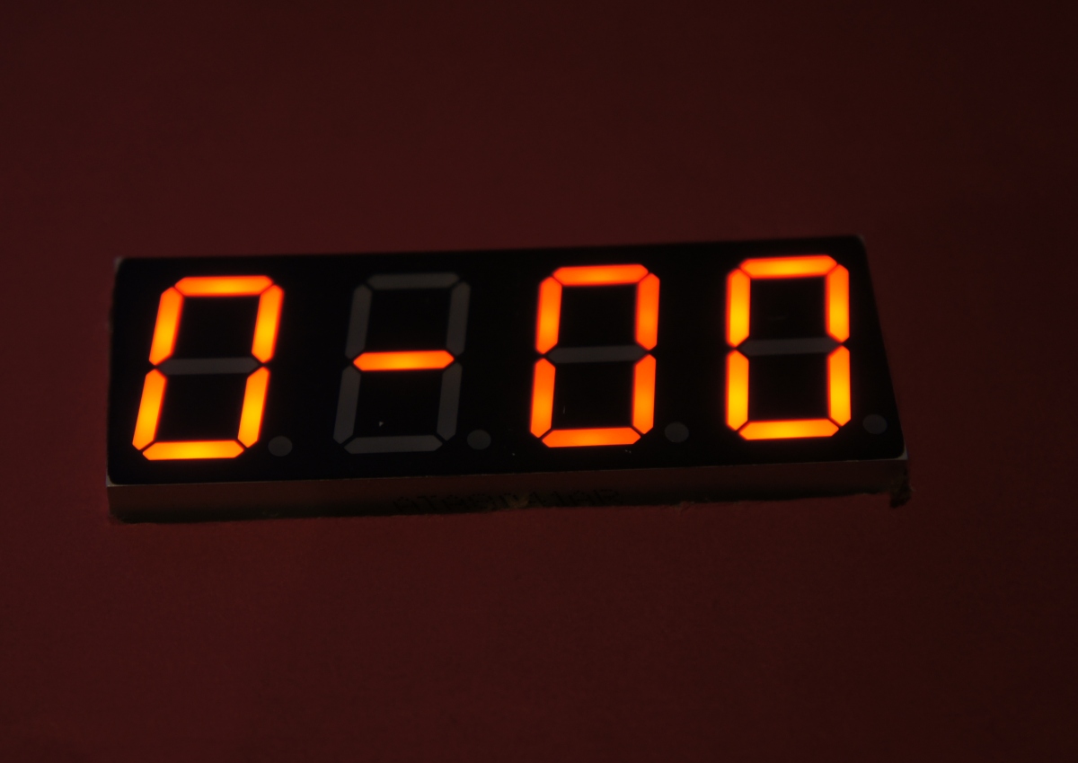
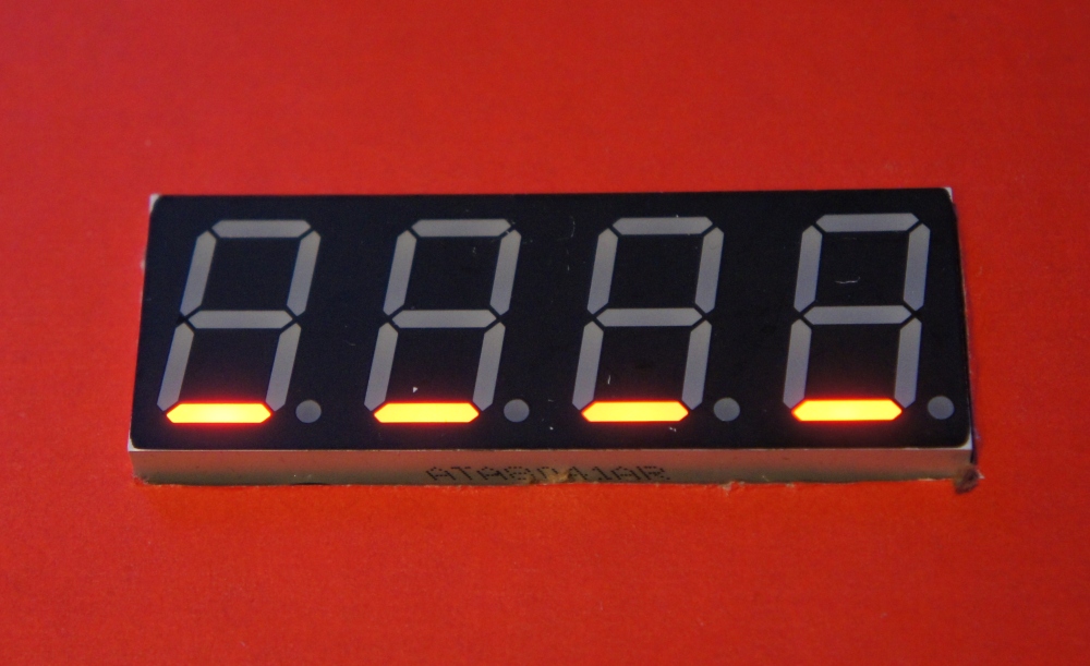
Once you see a rotating display of 0-00 you will know the device has been reset to 9600bps. You can now release the RX pin from ground, and the display will continue to function normally.
There is also an example sketch to show you how to do a reset over serial. This can be handy if the display is installed in an application and you can’t pull the RX line low during power up.
Resources and Going Further
You should now be able to control the OpenSegment with serial and a few other methods. Be sure to checkout the example code and datasheet for more information.
Now that you’ve got the OpenSegment board figured out, you should consider reading about:
- SPI Communication
- Buttons
- Pull-up resistors
- Learn how to use GitHub and help us make OpenSegment better by requesting and adding new features!
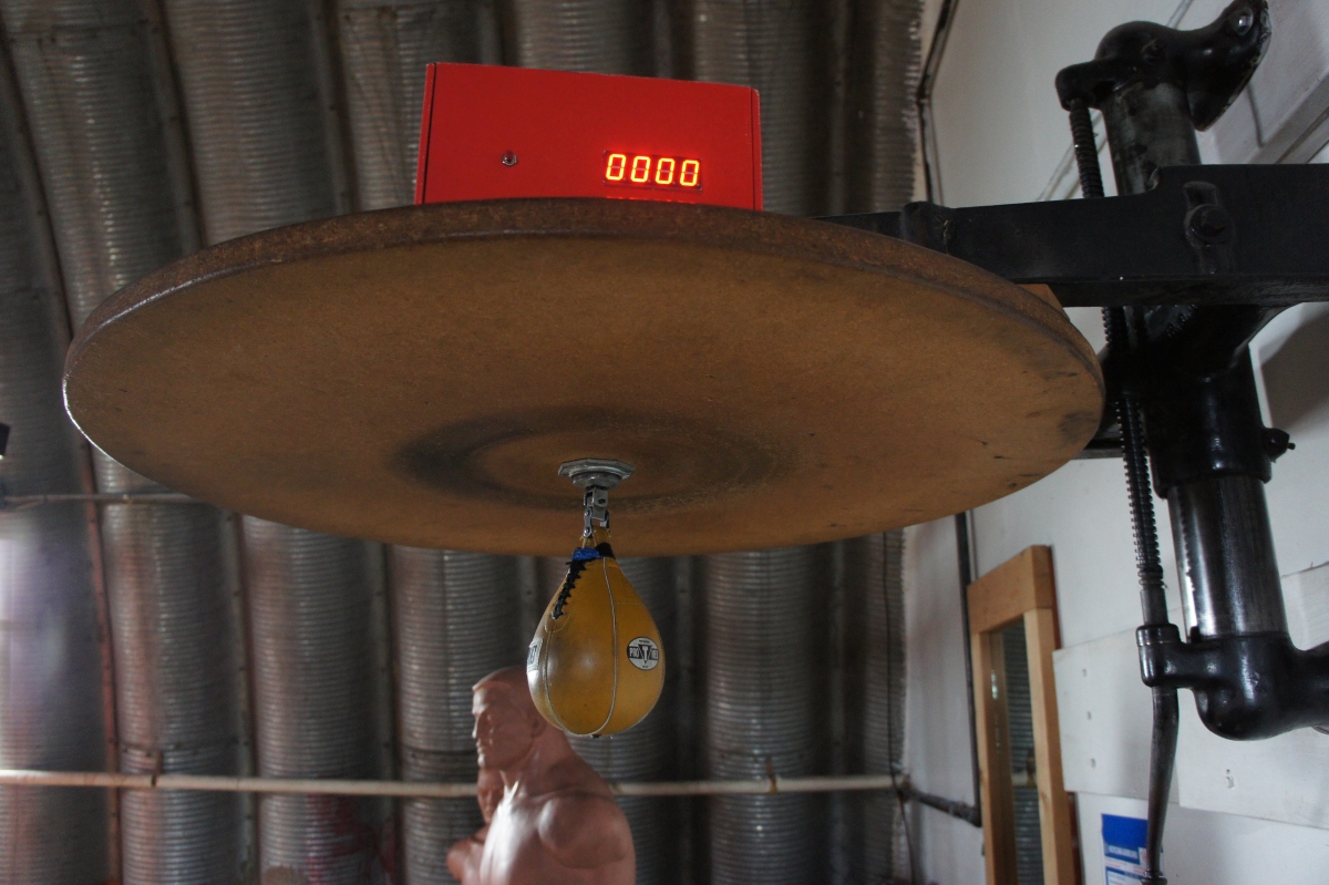
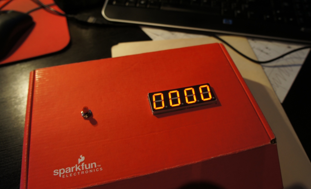
- Build your own Reaction Timer, complete with OpenSegment display.