Understanding Thermal Resistance
 Alex the Giant
Example: SMD DC/DC Converter
The board we’re using is the Buck-Boost, which uses the TPS63070 DC-DC converter. The board is 1.25x1.25 inches using 1oz copper. Other things to note, is the regulator is in the center of the board, and is over 95% solid copper. Because of the size, I’m going to make some assumptions by using the total board area for the thermal resistance, and use all 41 vias for the via thermal resistance.
To get started we need to figure out how much power we need to dissipate. With a DC-DC converter, the input current does not equal the output current, so we can’t use the same formula as we did for the linear regulator. Instead we can estimate using the efficiency graph from the datasheet:
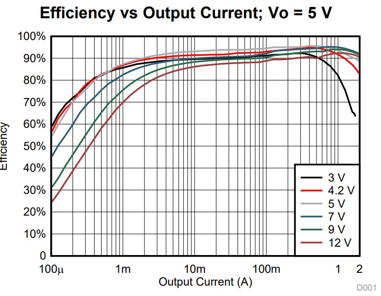
The efficiency graph plots the efficiency as a function of the output current, which is different based on the input and output voltages. For this test, we’ll use the same values before, having an input voltage of 12V and output voltage of 5V. This time though we’ll increase the load current to 1.0A. Using the 5V efficiency graph above, the efficiency should be around 93%, which would make our power loss 7% of the output power.

For the thermal resistances I used the via thermal resistance calculator and approximated the thermal resistance with the vias to be around 4.4°C/W using the values from the via calculation tool. To estimate the PCB thermal resistance, the board will be elevated off the table, to prevent using the table a heatsink. But because the bottom of the board is also in contact with the air, the surface area is now doubled from 10.08cm^2 to 20.16cm^2. Based on the surface area for the buck-boost board, I can estimate the PCBs thermal resistance to be around 65°C/W.

The datasheet for the TPS63070 has the following for the thermal characteristics:
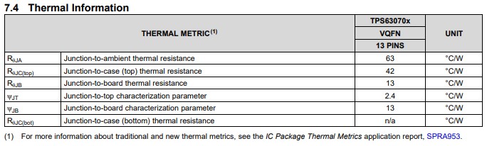
The junction to case thermal resistance is not applicable, however the junction to board thermal resistance is, which is around 13°C/W. Using the thermal resistance values, we can plug that into the junction temperature equation:


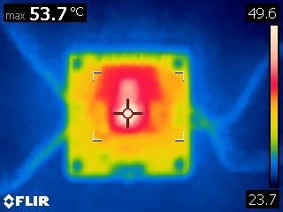
Just like before, I enabled the dummy load and let the board heat up until the temperature stopped rising. As shown below, I recorded a temperature of around 54°C.