Understanding Thermal Resistance
 Alex the Giant
Example: PTH Linear Regulator
Let’s see how well the thermal resistance calculations work in the real world. For these examples I’m going to use two different kinds of voltage regulators, a linear regulator, specifically the LM7805, as well as a DC-DC converter. We’ll see how well they stand up to the numbers we get from the datasheets.
Linear Regulator
Having a low cost and low noise voltage regulator, how can you go wrong? Linear regulators are a great choice for many applications, but where they fall short is their efficiency. We can see the basic design of a linear regulator below:

To determine how hot a linear regulator will get, let’s start with the understanding that the input power must equal the output power. Ideally, the system would be 100% efficient, but in the real world there are going to be some losses, and that power loss is dissipated in the form of heat (PD). This can be expressed as the following formula:
This means that the power dissipated can be expressed as:
In electronics power can be expressed as the product of the voltage and current. Which means we can rewrite the first equation as:

Now we need to look at the thermal characteristics of the linear regulator. The LM7805, has the following thermal resistances for the TO-220 package being used:
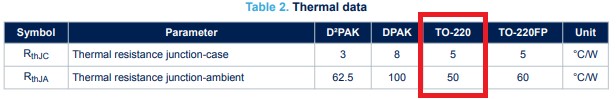
Without a heatsink (RθJA)
For this first example, we’ll see how hot a linear regulator gets with only a 200mA load. TheLM7805 has an output voltage of 5V, and the input voltage will be around 12V. Plugging those numbers into our power loss equation from above, gives us:


To figure out how hot that will get without a heatsink, we’ll need to use the Junction to Air thermal resistance, which is 50°C/W. Using the formula from the thermal resistance section, and assuming ambient air temperature is 23°C, we can calculate the junction temperature to be:


To see how that compares to the real world, I measured the input voltage to be 12.1V and the output voltage under load to be 4.90V. I used a constant current dummy load set to 200mA connected to the output. Using the measured values, the dissipated power is:

The expected junction temperature should then be:

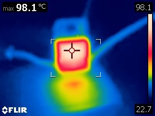
As the thermal image above shows, after turning on the load and letting the regulator heat up, it settled at a temperature of around 98°C. Pretty close, but it’s a good example of why it’s important to add margins to numbers. Due to the lack of precision, the power supply was slightly higher than we calculated, and under load, the regulator has a output voltage tolerance of 4%, which could allow the output voltage to drop to as low as 4.8V and still be in spec.
With a Heatsink (Using RθJC)
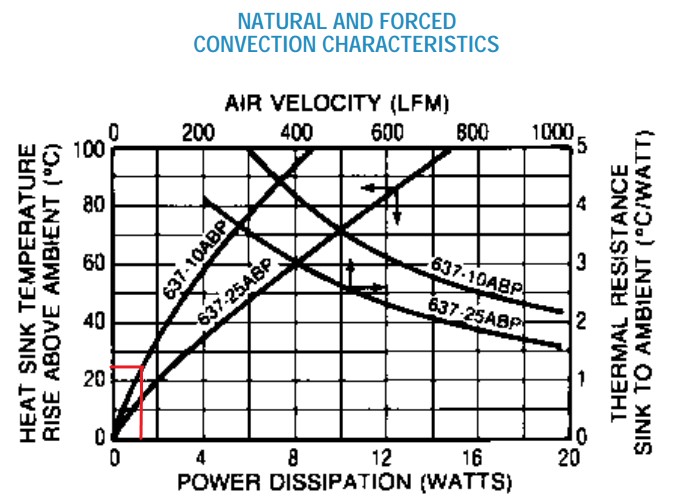
Now with the addition of a heatsink, instead of using the thermal resistance from the junction to air, we need to use the value for junction to case, which is around 5°C/W. After looking at the datasheet for the heatsink I’m using, ~1.4W of power in free air would result in a 25°C temperature rise:
Because the heatsink provides a temperature rise instead of a thermal resistance, We will need to first calculate the junction temperature rise using the thermal resistance from the junction to the heatsink, and then add on temperature rise from the heatsink and ambient air temperature to get the junction temperature. Using thermal compound lowers the thermal resistance from the case to the heatsink (~0.25°C/W), without it we'll assume the thermal resistance is around 1°C/W. The junction temperature equation therefore becomes:


The actual voltages were the same as without a heatsink: Vin = 12.10V, Vout = 4.90V, Iout = 200mA. This resulted in the same 1.44W of power that actually needed to be dissipated, which only increased the calculated junction temperature to 56.64°C. After turning on power and enabling the load, I waited to let the temperature get up to a steady state temperature and measured the temperature of the regulator to be around 54°C.
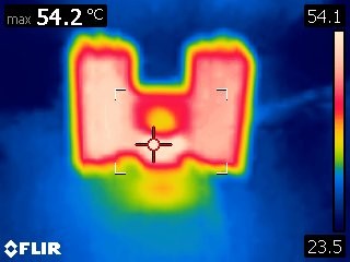
This time the temperature was lower than we calculated. Most likely the error came from reading the temperature rise in still air for the heatsink, instead of 25°C, it could have been closer to 23°C. In the last example we’ll use a surface mount regulator and try to estimate how hot the regulator gets using the PCB as a heatsink.