TSL2561 Luminosity Sensor Hookup Guide
This Tutorial is Retired!
This tutorial covers concepts or technologies that are no longer current. It's still here for you to read and enjoy, but may not be as useful as our newest tutorials.
 MikeGrusin
Let There Be Light!
The TSL2561 is an inexpensive, yet sophisticated, light sensor. Unlike simpler sensors, like photoresistors and photodiodes, the TSL2561 incorporates both infrared and visible light sensors to better approximate the response of the human eye. Because the TSL2561 is an integrating sensor (it soaks up light for a predetermined amount of time), it is capable of measuring both very small and very large amounts of light.
This hookup guide will explain what this sensor does and how you can use it in your projects. Let's get started!
What is lux? (Baby don't hurt me...)
With a bit of math, the TSL2561 can output illumination in lux. Technically, one lux is equal to one lumen per square meter. Practically, lux is a measure of how bright any given illumination will appear to the human eye.
The human eye has a huge dynamic range, far more than most electronic sensors. Real-world conditions can range from 0.0001 lux in starlight, to over 100,000 lux in direct sunlight. The TSL2561 has features that allow it to handle this huge dynamic range. These settings are similar to a camera; one can change both the sensitivity, which is like an ASA film rating, and the integration time, which is like the shutter speed. Like a camera, you can balance those measurements for the best results.
Lux is a very complex measurement to make because it involves both the human eye's response to color (frequency) and the concentration of that light (a flashlight will produce a higher lux value than the equivalent bare bulb). The TSL2561 is not a true luxmeter, but the manufacturer of the TSL2561 has characterized its output against professional equipment to come up with lux approximation equations. (You can find these equations in the datasheet, and we're also using them in our software library.) It should be noted that although these equations will get you in the ballpark, the TSL2561 is not a calibrated instrument (nor is it priced like one). If you need highly accurate results you should at least perform your own calibration. For everyday use however, the TSL2561 is far superior to simpler photoresistors and photodiodes for illumination measurement.
Covered in This Tutorial
We will show you how to connect this sensor to an Arduino microcontroller, and use the included software library to get measurements out of the sensor. If you're using a different type of microcomputer these instructions and source code may still be helpful.
Suggested Reading
Installing the Arduino Library
Libraries are collections of software functions geared towards a single purpose, such as communicating with a specific device. Arduino comes with a number of built-in libraries that help you do advanced tasks. We've written an Arduino library called SFE_TSL2561 that allows you to easily talk to the TSL2561 sensor. This library is not included with the stock Arduino software, but don't worry, installing new libraries is easy.
If you'd like to interface the TSL2561 to a microcontroller other than an Arduino, the C++ source code in the library and the information in the datasheet may be helpful when writing your own code.
1. Install the Arduino IDE
If you don't already have the Arduino IDE (Integrated Development Environment) installed, download the version for your system (Windows, Mac, Linux) from http://arduino.cc/en/Main/Software and install it following the instructions on that site.
If you need help installing the IDE, check out our tutorial.
2. Install the SFE_TSL2561 library
User-installed libraries live in a "libraries" folder within your personal Arduino sketch folder. On Windows systems your personal sketch folder is located in "My Documents/Arduino". On Mac computers, it's "~/Documents/Arduino". On Linux it is usually "~/Arduino/sketchbook". Locate your personal Arduino sketch folder and open it so you can drag new files into it.
Now download the latest TSL2561 software archive from https://github.com/sparkfun/TSL2561_Luminosity_Sensor_BOB. Look for and click the "Download ZIP" button and save the file to your system.
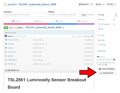
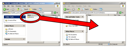
When you open the .zip file you just downloaded (on most systems you should be able to double-click it to show the included files), you'll see several folders. Drag the "libraries" folder from the .zip folder into your personal Arduino sketch folder. If you get a warning that there is already a libraries folder there, that's fine. (It just means you've already installed some libraries, which is great!) Just tell your system to go ahead and overwrite them, which sounds alarming but will only add the new library to the existing folder.
That's it! Now restart the Arduino IDE and you should be ready to go.
If any of these instructions are unclear, you can find more detailed instructions in our installing an arduino library tutorial.
Connecting the Hardware
This guide covers connecting the TSL2561 Luminosity Sensor to an Arduino microcontroller. If you're using a different microcontroller, don't panic. Many microcontrollers have an I2C interface, and you can use this library, datasheet, and example code to help you write you own code.
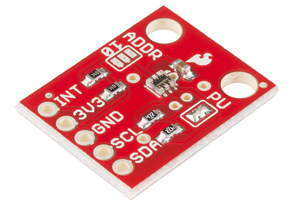
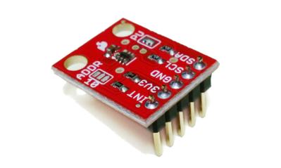
Connection names
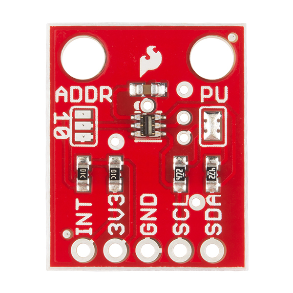
Breakout boards "break out" or connect the tinier pins on tiny components to larger connection points that we humans can deal with. (Robots are welcome to deal with the parts directly.) Breakout boards will also often include support components like resistors and capacitors that make the boards easier to use.
The TSL2561 Breakout Board breaks out five connections that we traditionally call "pins" but are actually holes that you can solder wires or header pins to.
You'll connect four of the five pins on the board to your Arduino. The four pins you need are labeled 3V3, GND, SCL, and SDA.
The fifth pin, INT is an optional interrupt signal which the TSL2561 can use to "interrupt" your microcontroller. You can set up the TSL2561 to automatically send an interrupt when it completes a measurement, or if a measurement goes above or below a certain level for a certain amount of time. This pin is not needed for the basic operation of the TSL2561.
Wiring up the board
You can use any method you like to make your electrical connections to the board. For this example, we'll solder on a five-pin length of male-male header strip, and use male/female jumper wires to connect the TSL2561 to an Arduino.
Step 1: Solder a 5-pin length of male-male header to the board. You can solder it to either side; the bottom is more useful for breadboards, and the top is more useful for jumper wires.
Step 2: There is no step 2.
Connecting to your Arduino
When you're done soldering, connect the 3V3, GND, SCL, and SDA pins to your Arduino. Different Arduino models use different pins for the I2C interface; use the following chart to determine where to plug everything in.
IMPORTANT: Connect the power pins (3V3 and GND) ONLY to a 3.3V supply. Larger voltages will permanently damage the part. Note that because I2C uses open drain drivers, it is safe to connect the I2C pins (DA and CL) to the I2C port on a 5V microprocessor.
| TSL2561 label | Pin function | Arduino connection | ||||||
| SDA | I2C data |
pin labeled SDA, or:
|
||||||
| SCL | I2C clock |
pin labeled SCL, or:
|
||||||
| GND | Ground | GND | ||||||
| 3V3 | 3.3V power supply | 3.3V (NOT 5V) | ||||||
| INT | Interrupt | Optional, leave disconnected unless you're using interrupts. |
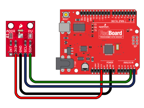
Once you have the TSL2561 connected to your Arduino, we're ready to play with the software.
Using the Arduino Library
Hopefully at this point you've installed the SFE_TSL2561 library, and connected the hardware to your Arduino. Now we're ready to measure some photons.
Running the example sketch
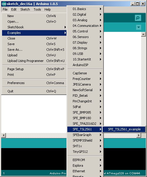
The library you just installed includes an example sketch that shows the basic operation of the TSL2561.
After you install the library, run the Arduino IDE, and open the following menu item: File / Examples / SFE_TSL2561 / SFE_2561_example.
(If you don't see this menu item, you may not have installed the library correctly, or didn't restart the Arduino IDE. Take another look at the library installation page to see if you missed any steps.)
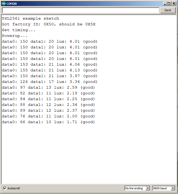
When the example opens, upload it to your Arduino and open the Serial Monitor to 9600 baud. You should see some diagnostic information (if it can't find the device, double check your hardware connections) followed by raw data and lux readings. (See the first page of this tutorial for information on lux.)
Settings
There are two settings you can make to control the sensitivity of the TSL2561.
Integration time
The TSL2561 is a bit like a camera with a shutter. The sensor will soak up light as long as the shutter is open. You can open the shutter for a brief period if there's plenty of light, or you can keep the shutter open for a long time to capture dim objects like stars. The amount of time the shutter is open is called the integration time.
The default integration time is 402ms ("ms" stands for milliseconds. One ms is 1/1000 of a second, so 402ms is about 0.4 seconds.) In addition to the default integration time of 402ms, there are also built-in settings for shorter times of 101ms and 13.7ms. Shorter integration times will let less light into the device, which is better for bright conditions. Longer integration times will let more light into the device, which is better for dim conditions.
Gain
In addition to the integration time, there are two gain levels you can choose between. The default setting is X1. There is also an X16 setting, which has sixteen times the sensitivity of X1. To continue the camera analogy, this would be like using ASA 100 speed film (X1), which is good for bright conditions, or ASA 1600 speed film (X16) which is better for night scenes.
The example sketch sets up the default integration time of 402ms, and uses the default gain of X1. You can easily change these settings in the example sketch (see the comments), and upload the modified sketch to try out your new settings.
Too much light?
Note that if there is too much light, one or both of the TSL2561's sensors will "saturate", which means that they're at the maximum possible reading and can't go any higher.
The internal sensor registers are 16 bits wide, which means they can hold numbers from 0 to 65535. (Fun fact: 65535 is 1111 1111 1111 1111 in binary.) Larger numbers just won't fit, in the same way you can't fit 100 into two digits.
If there's more light present than the sensor can measure, the register will peg at the maximum 65535 value. If this happens, the example code will show one or both of the raw sensor readings at 65535, the lux will be 0.0, and the reading will be marked "BAD".
But all is not lost! You can reduce the sensitivity of the TSL2561 in several ways, either or both of which will get the light reading back down into the 0 to 65535 range.
The easiest way to reduce sensitivity is to reduce the integration time of the TSL2561. The default integration time is 402ms. You can easily change this to one of the shorter times of 101ms and 13.7ms. Shorter integration times will let less light into the device, causing a lower reading, which is good for bright conditions.
You can also change the gain setting. If you're using X16 and the sensor saturates, definitely change it to X1 which will let 16 times less light into the device. (Unfortunately if you're already at X1, you can't go any lower and must reduce the integration time.)
Too little light?
If you'll be measuring very small amounts of light, you should increase the integration time and/or sensitivity as much as you can (without saturating the sensors). This will improve the resolution you get at very small lux readings.
For example, at the lowest sensitivity, the resolution will only be about 0.9 lux. At the highest sensitivity, the resolution will be around 0.002 lux. (Note that this only involves the resolution, which is separate from accuracy.)
The maximum native sensitivity will be acheived at 402ms integration time and 16X gain.
However, if you're already using those settings and the device still isn't sensitive enough, you can try doing a longer manual exposure.
The above built-in integration times are fully automatic (the device handles its own timing), but you also have the option to perform your own manual integration. This requires you to start integration ("open the shutter"), wait for your desired time period, then stop the integration ("close the shutter"). This is less convenient and less accurate than the built-in settings, but may be useful for very low light levels. See the comments in the example sketch for how to do this.
Note that even in complete darkness, the sensor will still measure a small amount of intrinsic electrical noise that will limit the low end of the useful range. In other words, even if you do very long exposures, you may not be able to accurately measure extremely small amounts of light.
Writing your own sketches
The comments and code in the example sketch should get you started when writing your own sketches. In many cases you should be able to copy and paste the example code into your own.
Tips and Tricks
Things to watch out for
Give it the right voltage: The TSL2561 will operate on voltages from 2.7V to 3.6V. We recommend operating it at 3.3V. Never connect the "3V3" header to voltages higher than 3.6V!. Note that it is safe to connect the SCA and SDL pins to an I2C port on a 5V Arduino, as the pullup resistors on the TSL2561 board will keep the voltage below 3.6V.
Changing the solder jumpers
Solder jumpers are closely-spaced pads on a printed circuit board that are joined by blobs of solder to create an electrical connection. The TSL2561 breakout board has two such jumpers; you can add or remove solder from these pads to alter the functioning of the board.
To remove the solder from a solder jumper, cover it with solder wick, and carefully heat it with a soldering iron. When the solder melts, it will be absorbed by the wick. Remove the wick before the solder cools so it doesn't stick to the pads. If you didn't get all of the solder on the first pass, give it another try with a clean section of solder wick. When you're done you should be able to see a broken connection between the pads. While doing this be careful not to overheat the board (let it cool off between attempts), or the copper pads may lift from the board.
Disabling the I2C pullup resistors (PU)
The TSL2561 communicates with a host microcontroller via a communications standard called "I2C" (for Inter-Integrated-Circut). I2C uses two wires, usually labeled SCL (Serial Clock) and SDA (Serial Data). To function properly, I2C requires a pullup resistor on each of those lines. The TSL2561 Breakout Board includes these resistors. They're enabled by default, but you can disable them by clearing the solder jumper labeled PU.
I2C allows you to have multiple devices connected to the same two lines (collectively called a bus). The pullup resistors allow the bus to function, but you should only have one set of pullup resistors per bus.
If you have just one I2C device (such as the TSL2561 Breakout Board) connected to your microcontroller, the board is already set up properly. You don't need to change anything.
However, if you wish to connect more than one device to the bus, you should ensure that there is only one set of pullup resistors enabled on the bus. You do this by disabling every set of pullup resistors except one. (It doesn't matter where the enabled resistors live; they can be anywhere on the bus.)
To disable the I2C pullup resistors, remove all of the solder from the jumper labeled "PU". This jumper has three pads; be sure to separate all of the pads from each other. Remember that you'll need to ensure that another set of pullup resistors are enabled somewhere on the I2C bus.
To enable the I2C pullup resistors (factory default), add solder to bridge both sides of the "PU" jumper to the center pad. There should be one large blob of solder when you're done. Remember that you should only have one set of pullup resistors enabled on the entire I2C bus.
Note that you should not operate an I2C bus without pullup resistors. Aside from not functioning properly, the internal weak pull-up resistors in a 5V Arduino will pull the bus to 5V which may damage the TSL2561.
Changing the I2C address (ADDR)
Every component attached to an I2C bus has a fixed address from 0 to 127. You can theoretically have a maximum of 128 devices on a single bus, but in practice you are limited to the options available for each part.
The TSL2561 supports three possible addresses: 0x29, 0x39, or 0x49. Practically speaking, this means you can have up to three TSL2561s attached to a single I2C bus.
Which address the part uses is controlled by the solder jumper labeled "ADDR". When there is no solder on this jumper, the TSL2561 will used the default address of 0x39.
To use one of the other addresses, add solder to bridge the center pad to ONE of the two side pads. If you bridge to the "0" side, the address will be 0x29. If you bridge to the "1" side, the address will be 0x49. Don't bridge both sides.
Remember that you will need to inform the software library of the correct part address. This is done when you call the library's "begin" function. Here's an example with three light sensors:
SFE_TSL2561 LightSensor1; // Declare a TSL2561 called "LightSensor1"
SFE_TSL2561 LightSensor2; // Declare a TSL2561 called "LightSensor2"
SFE_TSL2561 LightSensor3; // Declare a TSL2561 called "LightSensor3"

void setup()
{
  LightSensor1.begin();     // Initialize LightSensor1 to address 0x39
  LightSensor2.begin(0x29); // Initialize LightSensor2 to address 0x29
  LightSensor3.begin(TSL2561_ADDR_1); // Initialize LightSensor3 to address 0x49
}
Note that in the begin() function, you can use:
- Nothing (empty parenthesis) for the default address (0x39)
- One of the existing address numbers (0x29, 0x39, 0x49)
One of the following predefined address names:
TSL2561_ADDR (0x39)
TSL2561_ADDR_1 (0x49)
TSL2561_ADDR_0 (0x29)
Resources and Going Further
If you have any questions or problems with the TSL2561, feel free to contact our Technical Support Department who will be happy to help you. You might also ask for advice in the SparkFun Forums, where customers help each other with their ideas and projects.
You may also wish to browse our tutorial library for interesting projects like the Weather Shield Hookup Guide that may lend themselves to the addition of an accurate light sensor.
Have fun with your new sensor!
- Your friends at SparkFun.