TPL5110 Nano Power Timer Hookup Guide
 Elias The Sparkiest
 Introduction
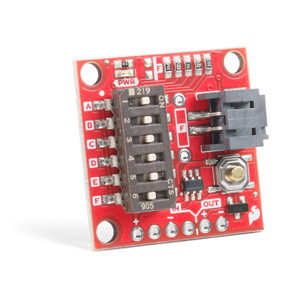
The TPL5110 Nano Power Timer is ideal for applications that require low power, and especially those projects that are running off of a LiPo battery. The Nano Power Timer will turn on your project, most likely a microcontroller, after the set amount of time, continuously. When your microcontroller has completed whatever needs doing, sampling air quality for example, it can then signal back to the Nano Power Timer to turn it off. While the project is off, the Nano Power Timer will only consume 35nA of power until the timer turns the project back on again. In this tutorial, we'll discuss how the time is set with the on board six DIP switch and use a microcontroller to turn it off when a task is finished.
Required Materials
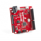
To follow along with this tutorial, you will need the following materials. You may not need everything though depending on what you have. For example, I chose the RedBoard as a simple demo, but you could use any microcontroller. Add it to your cart, read through the guide, and adjust the cart as necessary.


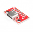
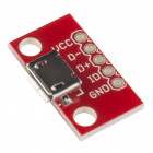
SparkFun Traveler microB Cable - 1m
CAB-14741Tools
You will need a soldering iron, solder, general soldering accessories, and a diagonal cutter.


Suggested Reading
If you aren’t familiar with the following concepts, we recommend checking out these tutorials before continuing.
Pull-up Resistors
How to Solder: Through-Hole Soldering
How to Power a Project
Button and Switch Basics
Hardware Overview
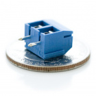
Power and LiPo Battery
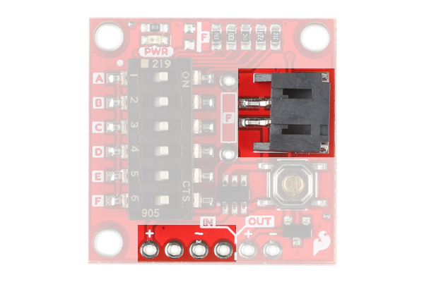
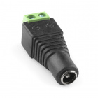
The Nano Power Timer can handle voltages between 1.8V - 5.5V and current up to 1.1 Amps. There are two options when connecting power to the Nano Power Timer. The first and more obvious option is the on board LiPo Battery Connector. The second is the VDD and GND pins on the five pin header underneath the IN label (short for INPUT). The power you provide to the INPUT side will flow out the OUTPUT side to power your microcontroller or project. If your using a LiPo battery, then do not attach another power source to these pins.
 |
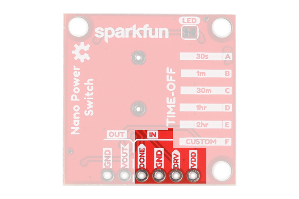 |
| Top | Bottom |
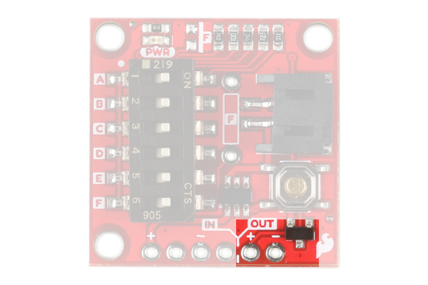
The OUT (OUTPUT) power is labeled VDD_OUT and GND. These pins will go to the board or project that you are powering.
 |
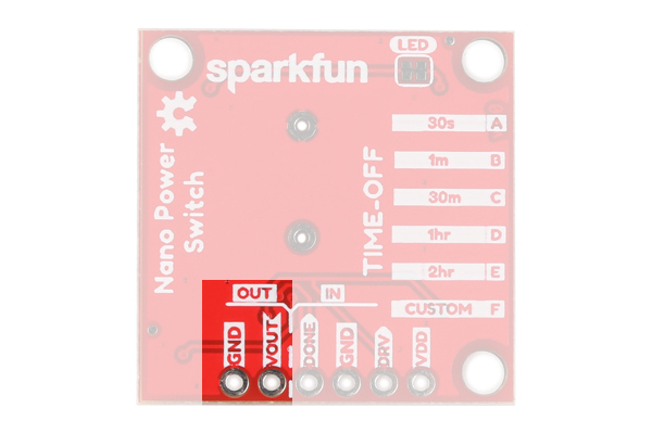 |
| Top | Bottom |
Timer and Delay Switch
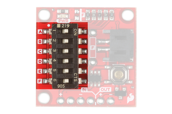
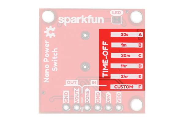
The Nano Power Timer's main function is to turn your microcontroller on after a set amount of time, continuously. The board has a six DIP switch that controls this time by changing resistance to the timer pin on the IC. To the left of the switch are five letters labeling each switch. On the underside of the board are these letters and the amount of time that is set when the corresponding switch is flipped.
 |
 |
| Top | Bottom |
This time is set when the board is powered up, so cycle power after you select your time. Check the table below to find a time suitable for your project.
| Timer | Switch | Resistance |
|---|---|---|
| 30 s | A | 16.2 kΩ |
| 1 min | B | 22 kΩ |
| 30 min | C | 93.1 kΩ |
| 1 hr | D | 124 kΩ |
| 2 hr | E | 169 kΩ |
| Custom | F | Custom |
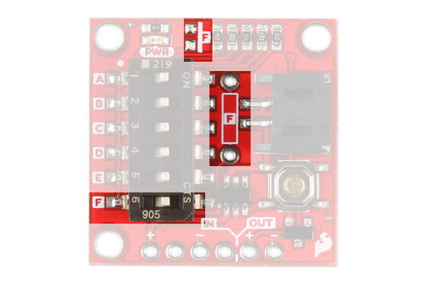
If you're time is not listed then we've left two additional pads for a custom time: one SMD and the other PTH. These two spaces are labeled with F on the product and their corresponding switch is labeled the same. If you decide to use them both at the same time their resistance is in parallel so make sure to calculate accordingly.
More Timer Options
You are not limited to the times that are represented on the silk. Ignoring the Custom switch option, there are 26 possible combinations of switches aside from the five printed on the board that yield times from three seconds up to 15 minutes. The chart below gives you the combination of ON resistors, their combined resistance, and their approximate time. A few redundant resistances were ommited.
| Timer | Switch Combo | Resistance |
|---|---|---|
| 2-3 s | A+B+C+D+E | 7.579 kΩ |
| 3-4 s | A+B+C+D | 7.933 kΩ |
| 4 s | A+B+C | 8.470 kΩ |
| 5 s | A+B+E | 8.844 kΩ |
| 6 s | A+B | 9.329 kΩ |
| 10 s | A+C+D+E | 11.563 kΩ |
| ~12 s | A+C+D | 12.407 kΩ |
| ~13 s | A+C+E | 12.742 kΩ |
| ~15 s | A+D+E | 13.225 kΩ |
| ~18 s | A+C | 13.774 kΩ |
| ~19 s | B+C+D+E | 14.243 kΩ |
| 20 s | A+D | 14.341 kΩ |
| ~22 s | A+E | 14.790 kΩ |
| ~25 s | B+C+D | 15.546 kΩ |
| ~28 s | B+C+E | 16.075 kΩ |
| 32 s | B+D+E | 16.852 kΩ |
| 35 s | B+C | 17.754 kΩ |
| 40 s | B+D | 18.707 kΩ |
| ~45 s | B+E | 19.479 kΩ |
| ~5 min | C+D+E | 40.400 kΩ |
| 8 min | C+D | 52.995 kΩ |
| ~12 min | C+E | 59.694 kΩ |
| 15 min | D+E | 72.033 kΩ |
Some of these times are approximate, but I have provided a Python script in the resources below to help you calculate what your exact time is. This will differ by small margins for each board due to the tolerance of the resistors.
Additional Timer Options From Datasheet
Below is the list of available times from the datasheet that are not included in the charts above. Of note are the timer options in the millisecond range. You can access these times by taking advantage of the two empty resistor pads on the Nano Power Timer.
| Timer | Resistance |
|---|---|
| 100 ms | 500 Ω |
| 200 ms | 1000 Ω |
| 300 ms | 1500 Ω |
| 400 ms | 2000 Ω |
| 500 ms | 2500 Ω |
| 600 ms | 3000 Ω |
| 700 ms | 3500 Ω |
| 800 ms | 4000 Ω |
| 900 ms | 4500 Ω |
| 1 s | 5.20 kΩ |
| 2 s | 6.79 kΩ |
| 7 s | 9.71 k Ω |
| 8 s | 10.18 kΩ |
| 9 s | 10.68 kΩ |
| 30 s | 16.78 kΩ |
| 50 s | 20.047 kΩ |
| 2 min | 29.35 kΩ |
| 3 min | 34.73 kΩ |
| 4 min | 39.11 kΩ |
| 5 min | 42.90 kΩ |
| 6 min | 46.29 kΩ |
| 7 min | 49.38 kΩ |
| 9 min | 54.92 kΩ |
| 10 min | 57.44 kΩ |
| 20 min | 77.57 kΩ |
| 40 min | 104.67 kΩ |
| 50 min | 115.33 kΩ |
| 1 hr 30 min | 149.39 kΩ |
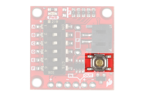
Push Button
The push button on the product will manually begin the timer. This allows you to test the timer and your project which should send an OFF signal to the Done pin.
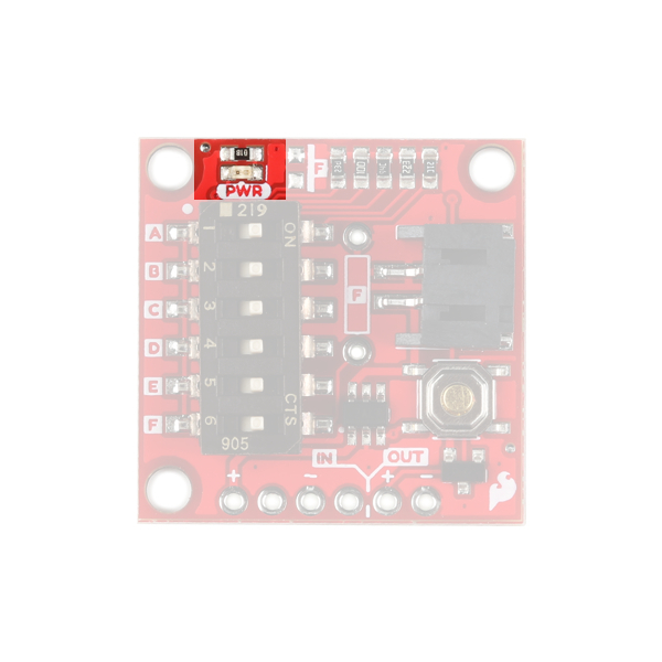
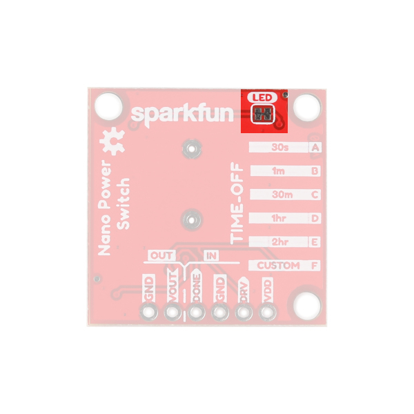
LED
There's a single red power LED on the topside of the product which indicates power is being supplied to the OUT pins. If you want to disconnect this LED, simply cut the trace between the jumper on the underside of the board labeled LED.
|
 |
| Power LED | Power LED Jumper |
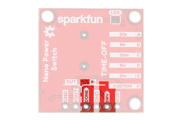
Header
Next to GND is the DONE pin that tells the product to turn your microcontroller or project off. To do this, your microcontroller or project will need to send a digital signal from LOW to HIGH to this pin. Finally, the DRV pin is active high and will start the timer of your project when the pin receives a HIGH signal. This is the same function as the on board push button. Not very many people will want to attach a different button, but if you wanted to, this would be the place.
How Do I Check the Exact Time?!
I've provided a simple Arduino sketch below to calculate the exact timing of the timer setting. You'll attach the VOUT pin to a digital I/O pin on your microcontroller and the sketch will start its timer when the power is high and end the timer when the power is off.
Hardware Hookup
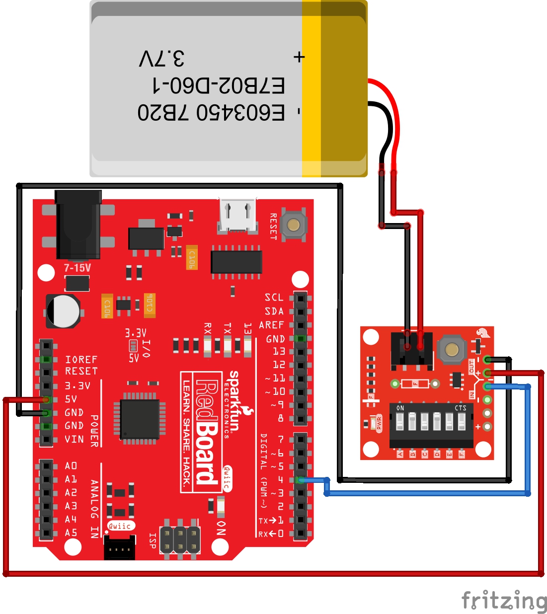
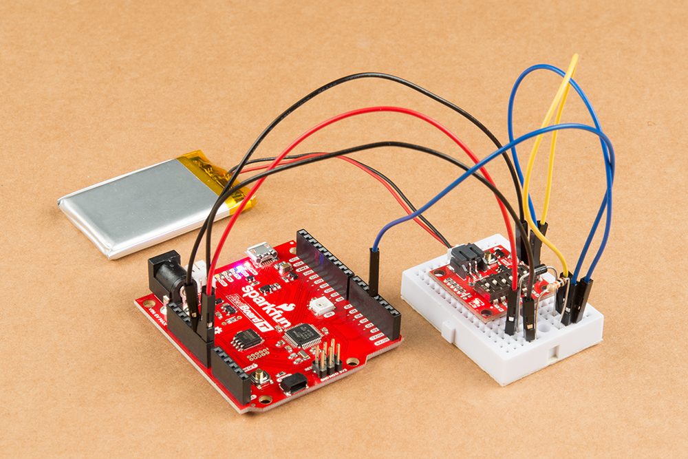
We're going to power a RedBoard Turbo with a 3.7V LiPo Battery and set it to a 14 second delay. By default, the board comes with every switch flipped to the ON position which is 3 second timer. To set the timer to 14 seconds, we'll turn some switches to the ON position and others to the OFF position. I used tweezers because the switches were too small for my hands.

To get a 14 second delay switches 'A' + 'D' + 'E' must be flipped ON, and the other swtiches flipped OFF. Next solder a 6 pin header of your choice to the Nano Power Timer. After the six pin header is soldered to the Nano Power Timer, plug in three wires into the female header as follows:
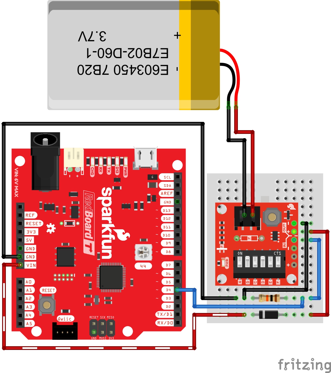
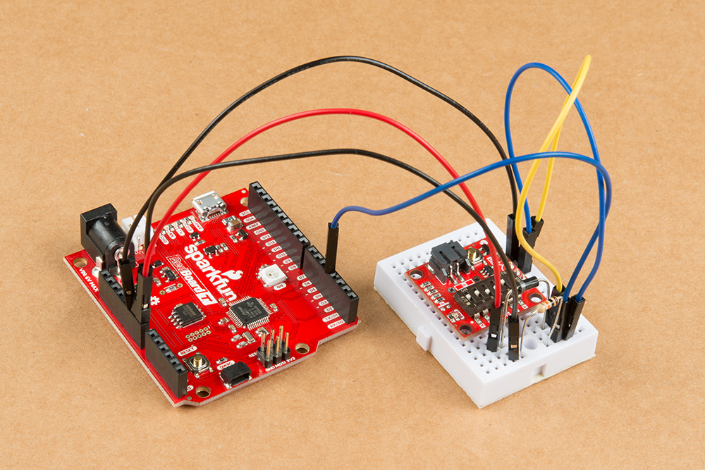
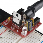
We'll use a Schottky diode to protect the TPL5110 when the RedBoard Turbo is connected to a computer when prototyping and uploading code. Additionally, we'll add a pull-down resistor on the Done pin. Depending on your microcontroller, you may not need resistor. After wiring your circuit together, you may have something similar to the image below without the battery connected.
Let's move onto the code.
Simple Example
With this example we'll be laying out the very basics of how the Nano Power Timer works. Copy the code and paste in the Arduino IDE. Select your board (in this case, the RedBoard Turbo), COM port, and hit the upload button to upload in the Arduino IDE.
The Nano Power Timer is powered by a LiPo Battery and will turn on a RedBoard Turbo every 14 seconds. The RedBoard Turbo will blink it's blue LED, and then send a done signal back to the Nano Power Timer, which will turn off the RedBoard Turbo.
language:c
/*
TPL5110_Blink_Demo_example.ino

  Simple Example Code for the TPL5110 Nano Power Timer Hookup Guide. This code
  simply blinks the pin 13 LED and writes pin 4 (donePin pin) high. This shift from
  LOW to HIGH of the donePin pin, signals to the Nano Power Timer to turn off the
  microcontroller.
  SparkFun Electronics
  Date: May, 2019
  Author: Elias Santistevan
*/

int led = 13; // Pin 13 LED
int donePin = 4; // Done pin - can be any pin.

void setup(){

  pinMode(led, OUTPUT);
  pinMode(donePin, OUTPUT);

}

void loop(){
  // Blink.
  digitalWrite(led, HIGH);
  delay(1000);
  digitalWrite(led, LOW);
  delay(1000);

  // We're done!
  // It's important that the donePin is written LOW and THEN HIGH. This shift
  // from low to HIGH is how the Nano Power Timer knows to turn off the
  // microcontroller.
  digitalWrite(donePin, LOW);
  digitalWrite(donePin, HIGH);
  delay(10);
}
After uploading this code, and plugging in the LiPo battery into the Nano Power Timer, the RedBoard Turbo will blink once, be turned off by the Nano Power Timer, and then will turn on again 12 seconds later (14 second timer - 2 second delay in sketch).
This Nano Power Timer really shines when you're doing remote projects that are running off of battery and you need to maximize the life of the battery! There's only so much deep sleeping that you can do in code, and nothing will compare to 35nA of power consumed in the off state of the Nano Power Timer. You just need one additional GPIO or some method of sending a digital signal that can go from LOW to HIGH to signal OFF to the Nano Power Timer.
Resources and Going Further
Now that you've successfully got your TPL5110 Nano Power Timer up and running, it's time to incorporate it into your own project! For more information, check out the resources below:
- Schematic (PDF)
- Eagle Files (ZIP)
- Datasheet (PDF)
- GitHub Repo
- /Firmware/Arduino
- /Firmware/Python
- SFE Product Showcase
Need some inspiration for your next project? Check out some of these related tutorials: