TFMini - Micro LiDAR Module (Qwiic) Hookup Guide
 bboyho
Hardware Overview
The sensor works by sending a modulated near-infrared light out. The light that is reflected from the object returns to the sensor's receiver. The distance between the two can be converted using the sensor by calculating the time and phase difference. The distance measured may vary depending on the environment and the reflectivity of object.
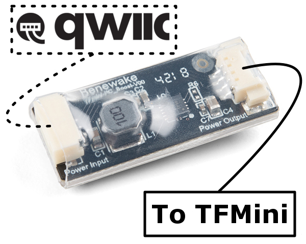
Input Power
According to the datasheet (pg 1), the input voltage is 5V. In this tutorial, we will be using the included boost converter by applying a 3.3V input voltage from the Qwiic side to boost power to 5V on the TFMini side.
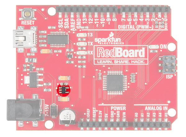
Make sure to use either the Beefy 3 with a 3.3V Arduino Pro Mini, RedBoard Qwiic, or the LD1117V33 3.3V voltage regulator to provide sufficient current for the TFMini. You may need to power the Qwiic TFMini with an external power supply.
Logic Levels
While the sensor can be powered at 5V, the I2C pins are only 3.3V logic. Make sure to use a logic level converter when reading the sensor with a 5V microcontroller.
Pinout
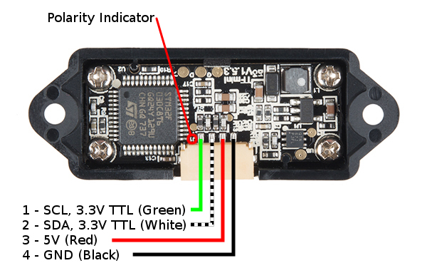
There is a marking next to the polarized connector to indicate the polarity as "J1" as indicated in the image below. This is useful when referencing sensor's pinout. As opposed to the original TFMini, the green and white wires for the Qwiic enabled TFMini uses an I2C serial. The default address of the TFMini is 0x10.
| Pin Number | Wire Color | Qwiic TFMini Pinout | Wire Color |
|---|---|---|---|
| 1 | Green | SCL (3.3V TTL) | Yellow |
| 2 | White | SDA (3.3V TTL) | Blue |
| 3 | Red | 5V | Red |
| 4 | Black | GND | Black |