TFMini - Micro LiDAR Module (Qwiic) Hookup Guide
Contributors:
 bboyho
bboyho 
Hardware Hookup
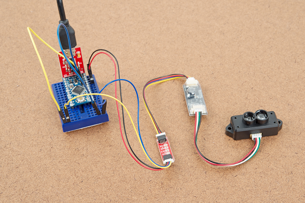
If you haven't yet assembled your 3.3V Pro Mini, now would be the time to head on over to that tutorial to solder the header pins. Once soldered, connect the power and I2C pins between the Arduino Pro Mini 3.3V/8MHz and Qwiic adapter.
| Arduino Pins | Qwiic Adapter Pins | Wire Color |
|---|---|---|
| A5 (SCL) | SCL (3.3V TTL) | Yellow |
| A4 (SDA) | SDA (3.3V TTL) | Blue |
| 3.3V | 3.3V | Red |
| GND | GND | Black |
Then connect the Qwiic cable that was included in the Power Input side between the Qwiic adapter and the boost circuit. On the other side, insert the second cable that was included in the Power Output side between from the boost circuit to the TFMini. The connectors are different on each side of the boost converter so it should not be Finally, power the circuit up with a micro-B USB cable and the Beefy 3. The connection should look like the image below.
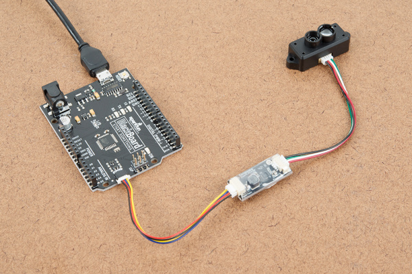
Tip: Looking to reduce the number of components? Try using the SparkX BlackBoard or RedBoard Qwiic is an alternative to connecting to the Qwiic enabled TFMini. The trade off is that the BlackBoard is larger than the Arduino Pro Mini.

Tip: Remember, powering from a USB port can only provide about 500mA. When testing this between short and intermediate distances, the Beefy3 was sufficient enough to power both the Arduino Pro Mini 3.3V and Qwiic TFMini. You may need an external power supply when powering both at longer distances.
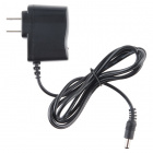
If you are using a SparkX BlackBoard or RedBoard Qwiic with a USB cable, try powering the boards with a 9V wall adapter in addition to USB. Don't worry, it is acceptable to connect both a barrel jack and a USB connector at the same time. The boards have power-control circuitry to automatically select the best power source.
 Retired
If you are using a SparkX BlackBoard or RedBoard Qwiic with a USB cable, try powering the boards with a 9V wall adapter in addition to USB. Don't worry, it is acceptable to connect both a barrel jack and a USB connector at the same time. The boards have power-control circuitry to automatically select the best power source.