TEMT6000 Ambient Light Sensor Hookup Guide
 Michael Bartlett
 Introduction
Light sensors have all sorts of practical uses in the modern era, most notably in devices with auto-brightness for their screens and in digital cameras to adjust exposure. With the Ambient Light Sensor Breakout, it's be a breeze to interface with the TEMT6000 Light Sensor so you can bring the ability to detect light levels to any project.
As the name suggests, the TEMT6000 Light Sensor will detect the brightness of its surroundings. While there are many properties of light that can help us categorize its brightness, the TEMT6000 measures illuminance (measured in lux (lx), often denoted Ev). Don't worry if illuminance is new to you though, the TEMT6000 is very intuitive to use: brighter = more current, darker = less current.
In this guide, we’ll show you how to quickly get the ambient light sensor breakout up and running, then discuss some of the more technical details of how it functions. After that, we’ll show you how to use it to make a practical DIY nightlight!
Required Materials
Here's what you'll need to follow along with this guide:
Suggested Reading
- Check out our Light Tutorial for more information on the technical properties of light. An intuitive understanding of light should be enough to make use of the TEMT6000, but, if you're looking for more precise applications, this is worth the read.
- This sensor is a phototransistor. Knowing how transistors work will be helpful in using the TEMT6000.
- A voltage divider circuit is used to create a usable signal from the light sensor for a microcontroller. A basic understanding of voltage dividers is recommended.
- To read the voltage coming from the voltage diverer circuit, an Analog to Digital Converter (ADC) will be necessary. This tutorial will show how to read the voltage on the ADC found on an Arduino microcontroller.
- We recommend soldering some male header-pins to your TEMT6000 breakout to make it easier to use, so be sure to read our Soldering Tutorial for details on good soldering practice.
- Knowing more about the TEMT6000 itself couldn't hurt, so here's a link to its datasheet.
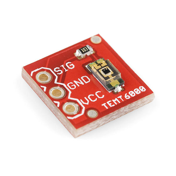
Hardware Overview
As you can see from the image below, the TEMT6000 is about as simple as it gets when it comes to breakout boards. The three pins broken out are labeled on the top of the board.
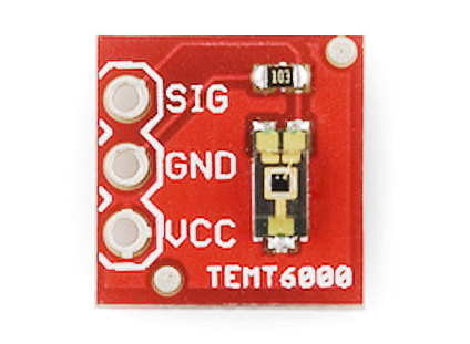
The function of each pin can be found in the table below.
| Symbol | Description |
|---|---|
| SIG | Output Voltage from the divider circuit |
| GND | GND (0V) |
| VCC | Collector Voltage (should not exceed 6V) |
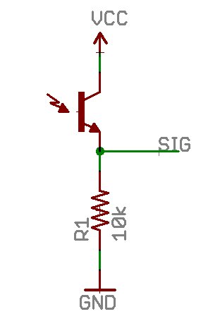
Being a phototransistor, this sensor acts just like any other NPN transistor -- the greater the incoming light on the Base, the the more current that can flow from the Collector to the Emitter. Only light that falls within the visible spectrum (390–700 nm) will alter the Base. Infrared, ultraviolet, or any other light we can’t directly see will have no effect on the sensor.
This sensor can handle voltages from both 5V and 3.3V devices.
To make taking light measurements as easy as possible, this sensor has been designed into a voltage divider circuit. The TEMT600 acts as one of the resistors in the divider, and, as the light hitting it changes, so too does the voltage on the SIG pin. To read that voltage, simply connect the SIG pin on the TEMT6000 to any analog to digital conversion pin on your microcontroller.
The voltage value returned from the SIG pin will vary depending on what voltage is being used to power the sensor and depending on the resolution of your ADC.
Hardware Assembly
First, let's fire up our light sensor and start collecting readings from it.
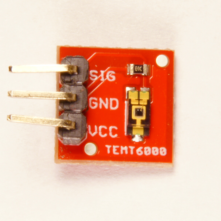
We recommend soldering male header-pins to the breakout to make it simpler to prototype with:
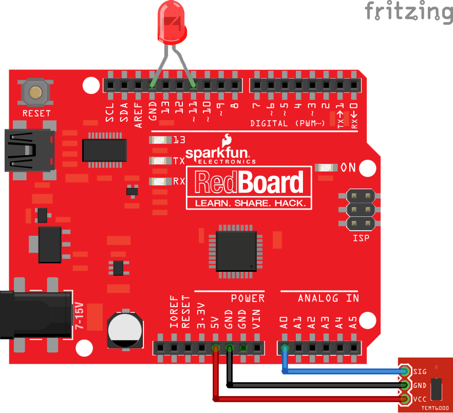
The rest is just plugging parts into the RedBoard. Start by taking any basic LED of your preferred color and placing its anode leg (the long leg) into a pin whose label is followed by a ~. This mark on the RedBoard means the pin supports pulse-width modulation (PWM), which is just a technical way of saying we can control the voltage output of the pin digitally; in this case it lets us control the apparent brightness of our LED. We want this because our LED is going to show us the relative brightness of the world through the eyes of our TEMT6000. If you're using a different board, be sure to read its documentation closely to see which of its pins support PWM. Place the other leg into ground (GND).
We used pin 11 on the RedBoard because it is the PWM pin closest to a ground pin. Thus, we didn't have to deform our LED's legs too much. This is the pin we'll be using in the sample code, so be sure to modify that constant if you're using a different physical pin.
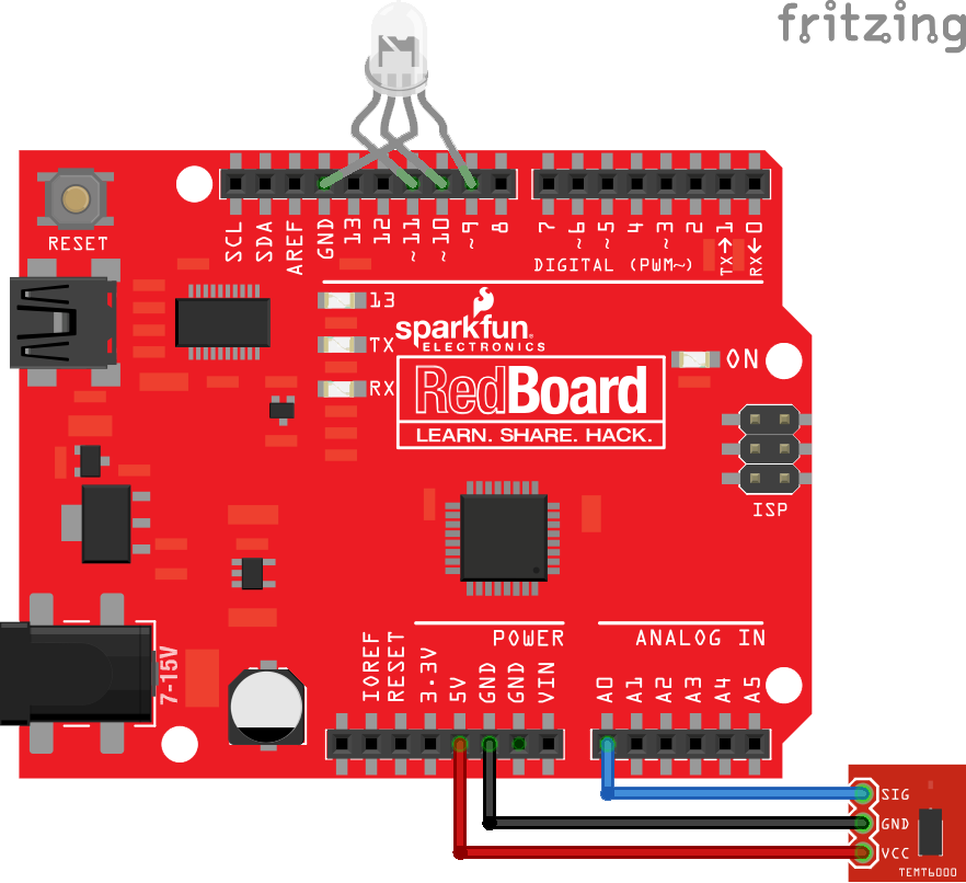
Next comes the light sensor breakout. Start by connecting the female ends of some male-to-female jumper cables to the pins we soldered to it earlier. Connect VCC on the sensor to the 5V pin on the RedBoard, GND to GND, and SIG to any analog pin (we'll be using A0 in the sample code). Use the table below to aid in wiring.
| TEMT6000 Pin | Arduino Pin |
|---|---|
| SIG | A0 |
| GND | GND |
| VCC | 5V |
Here's a diagram of how the circuit should look:
Programming
Now we're finished with the hookup, it's time to upload some.
Note: This example assumes you are using the latest version of the Arduino IDE on your desktop. If this is your first time using Arduino, please review our tutorial on installing the Arduino IDE.
If you have not previously installed an Arduino library, please check out our installation guide.Using the mini-b USB cable, hook the RedBoard up to a computer with the Arduino IDE installed. Select the appropriate COM port, select Sparkfun RedBoard as your target device, and then upload the following code:
language:c
#define LEDPIN 11         //LED brightness (PWM) writing
#define LIGHTSENSORPIN A0 //Ambient light sensor reading

void setup() {
  pinMode(LIGHTSENSORPIN,  INPUT);
  pinMode(LEDPIN, OUTPUT);
  Serial.begin(9600);
}

void loop() {
  float reading = analogRead(LIGHTSENSORPIN); //Read light level
  float square_ratio = reading / 1023.0;      //Get percent of maximum value (1023)
  square_ratio = pow(square_ratio, 2.0);      //Square to make response more obvious

  analogWrite(LEDPIN, 255.0 * square_ratio);  //Adjust LED brightness relatively
  Serial.println(reading);                    //Display reading in serial monitor
}
Once everything's uploaded, your LED should respond to the relative brightness that's exposed to the TEMT6000. Here's how the end result should look:
Try oscillating the TEMT6000 towards the RedBoard's green "ON" LED to see the change.
How Light Detection Works
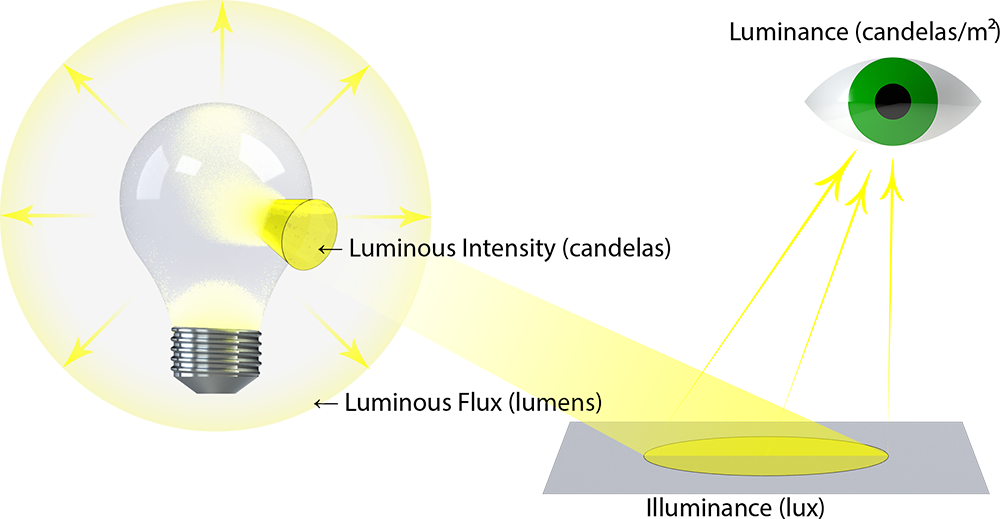
Now that our sensor is working, let's take a more in-depth look at what is going on inside the senor. As mentioned earlier, the TEMT6000 measures illuminance. If you're unfamiliar with illuminance, it is a measure of the total quantity of visible light emitted by a source (referred to as luminous flux, measured in lumens (lm) divided by an area in square meters. More notationally, 1 lx = 1 lm/m². Along with these, there are other properties of light that are unfortunately all named using the same Latin root for light, so it can be hard to keep them straight. Here's a diagram to hopefully elucidate the differences:
Why does the TEMT6000 measure illuminance? In most practices, measuring the intensity of light without factoring in distance is very difficult, and puzzled early astronomers for a long time. In short, there is apparent magnitude (how bright a source appears) and absolute magnitude (how bright the source actually is). Two sources of different absolute magnitudes can have the same apparent magnitude depending on their distance from the observer.
For example, if you have a bright source far away and a dim source very close, they can appear to have the same brightness because the brighter source's light will have to dissipate over a larger volume. This is why the sensor will read a smaller value if you move the same source of light farther away from it, essentially increasing the amount of space that the same amount of light has to fill between the source and the sensor (i.e. reducing the illuminance, as you're dividing by a larger surface area of the light-sphere generated by the source).
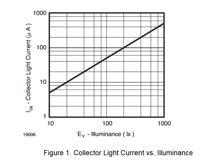
Here is a graphical relationship between the current (in µA) and illuminance of the immediate vicinity perceived by the sensor:
The TEMT6000 only recognizes light with wavelengths in the range of 390–700 nm, which roughly covers the entire spectrum of visible light. In other words, this won't pick up infrared, ultraviolet, or any other light we can't directly see.
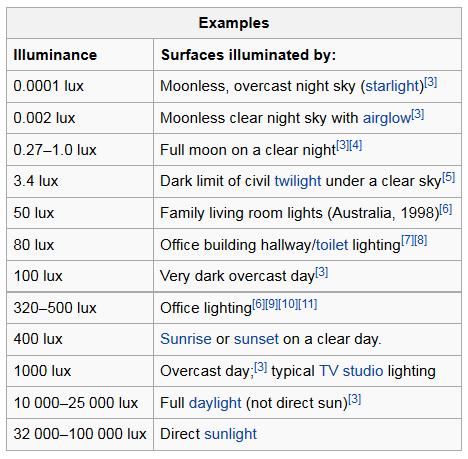
Here's a table of the typical illuminance from common sources of visible light:
Now that we understand the TEMT6000 a little better, let's use it in something more interesting and build ourselves a night light that turns itself on and off!
Example Project: Night Light
Required Materials
We'll be reusing a lot of parts from before. In fact, the only difference is we're upping the ante and using an RGB LED instead of a single color LED! Nevertheless, here's a list of everything you'll need:
Hookup
Since we're reusing a lot of the same parts, they're mostly going to occupy the same pins on the RedBoard: VCC on the breakout should connect to 5V on the RedBoard, GND to GND, and SIG to A0.
| TEMT6000 Pin | Arduino Pin |
|---|---|
| SIG | A0 |
| GND | GND |
| VCC | 5V |
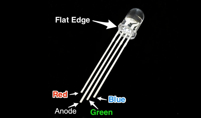
The main difference is now we have an RGB LED that has twice as many legs, but the idea is still the same. The longest leg on a common anode RGB LED is going to be the pin that goes to the GND pin. Most Arduino boards have a group of three consecutive PWM pins, and these happen to be pretty close to a GND. If the legs on your LED aren't bent too bad, you should be able to see which is the second longest leg—that's the cathode for the red LED, and that should go to pin 9. Plug the remaining two legs into pins 10 and 11 in the orientation they appear to go in easiest. Use the image below, if you can't tell the difference between the legs.
This table should clarify, which pins are connected.
| RGB LED Pin | Arduino Pin |
|---|---|
| Red Cathode | Pin D9 |
| Common Anode | GND |
| Green Cathode | Pin D10 |
| Blue Cathode | Pin D11 |
Here's what the setup should look like once everything is plugged in:
Programming
The code for this one is going to look a little different. The challenge is that we want to cycle through all the colors without being stuck in a loop and unable to read light values until the loop is done. The way around this is to use a function that will take a variable that counts and returns a color based on how far that variable has counted. This way, for every "count" (cycle of the loop) we have time to stop and check our TEMT6000 for a reading. There are some other little tricks that are explained in the comments.
The drill for uploading the code is the same as before.
language:c
#define LS_PIN A0  //Light Sensor pin
#define R_PIN  9   //Red pin
#define G_PIN  10  //Green pin
#define B_PIN  11  //Blue pin
#define POWER  4   /* Power to raise the ratio of read-value to largest read-value.
                    * Higher is less likely to be on during the day,
                    * but too high and it may not turn on once it's night.*/

#define TIME  500 /* The amount of milliseconds before taking a step through the color function.
                   * Higher values = slower transitions between colors.*/

uint16_t  _max =  0;  //Holds the largest brightness reading so far.
byte      count = 0;  //Keeps track of where we are on the color spectrum
float     ratio = 0;  //Stores the ratio of current brightness to largest recorded brightness.

void setup() {
  pinMode(LS_PIN,  INPUT);  //Reading in
  pinMode(R_PIN,  OUTPUT);  //Writing out*
  pinMode(G_PIN,  OUTPUT);  //*
  pinMode(B_PIN,  OUTPUT);  //*
  Serial.begin(9600);
}

void loop() {
  float reading = analogRead(LS_PIN); //Take brightness reading
  if (reading > _max) _max = reading; //See if it's the brightest so far

  /* Calculate the ratio between the reading and the max, raise the power, and average it with
   * the last reading to get our ratio but minimize flickering. */
  ratio = (ratio + pow(1.0 - reading / float(_max), POWER)) / 2.0;
  /* We're subtracting the ratio from 1 because we want brighter readings to result
   * in a dimmer display of colors, and smaller readings to result in brighter displays. */

  //Write the color from our spot in the spectrum at the relative brightness to the LED
  analogWrite(R_PIN, Rainbow(count + 170) * ratio);
  analogWrite(G_PIN, Rainbow(count + 85)  * ratio);
  analogWrite(B_PIN, Rainbow(count)       * ratio);
  /* Each color has the same pattern of increasing and decreasing brightness, just not synchronously.
   * We can reuse the same function and carefully offset each color to make sure we get to see all
   * the colors.*/


  if (!(millis() % TIME)) count++;
  /* There's a lot going on in this concise use of syntax. Essentially, whenever millis() (the
   * amount of milliseconds since the arduino has been on) is evenly divisble by TIME (i.e.
   * TIME milliseconds have passed) then the modulo operator (%) will return 0, which evaluates
   * as FALSE. The ! in front of the expression means invert, so this means every TIME milliseconds,
   * the expression will return TRUE. If it's TRUE, we take a step through the color spectrum. Bytes
   * can only count to 255 before they reset back to 0. The overflow of "count" is a passive way to
   * take us back to the start of the color spectrum without having to explicitly set "count" to 0.*/
}

/* Returns an appropriate value in 0-255 for a given value in 0-255. With good timing, it can be used
 * to cycle through the entire color spectrum. */
byte Rainbow(byte i) {
  if (i > 213) return i * 6;
  if (i > 127) return 0;
  if (i > 85)  return 255 - i * 6;
  return 255;
}
Once the code is uploaded, you should have yourself an automatic mood night light! Here's ours in action:
Resources and Going Further
- The TEMT6000 only detects the amalgamated presence of light with wavelengths in the range of 390–700 nm, but we've got a plethora of different light sensing options:
- Want a wearable version of the TEMT6000? You're in luck. Build a light-detecting garment, with the LilyPad Light Sensor.
- The TSL2561 Luminosity Sensor Breakout is an integrated sensor that can detect both visible light and infrared light.
- The ISL29125 RGB Light Sensor can detect light that is specifically red, green, blue, or any combination thereof.
- The ML8511 UV Sensor Breakout works similarly to the TEMT6000, but responds to ultraviolet light instead of visible light.
- The Mini Photocell is a very small alternative to the TEMT6000, however it is a photo resistor (a resistor that changes resistance based on the presence of light) instead of a phototransistor.
- If you plan on using the nightlight indefinitely, an energy-conscious suggestion would be to integrate a Wake on Shake. The Arduino will constantly be running and checking if its dark, which can use up a lot of energy over time. A Wake on Shake would make the current draw negligible until you bumped the circuit. This way you can easily activate the light in the dark if you need it, and would practically be off otherwise.
- Want a night light for outdoors? The Sunny Buddy makes keeping a battery charged with solar energy easy. Your night light could store energy during the day, and light the way for you at night! Of course you may want to also invest in a transparent plastic case to keep the elements out.
Or, you can check out these other great light-based tutorials.