STK-node
 D___Run___
 Introduction: SIK RedBoard & SparkFun Tinker Kit
This SparkFun Tinker Kit Experiment Guide is your map for navigating the waters of beginning embedded electronics, robotics and citizen science using the SparkFun RedBoard while sticking to a strict budget. This guide contains all the information you will need to explore the 11 circuits of the SparkFun Tinker Kit. At the center of this guide is one core philosophy -- that anyone can (and should) play around with cutting-edge electronics in a fun and playful way while not breaking the bank.
When you're done with this guide, you'll have the know-how to start creating your own projects and experiments. From building robots and game controllers to data logging, the world will be your oyster. Now enough talking -- let's start tinkering!
Included Materials

Here are all of the parts in the SparkFun Tinker Kit:
- SparkFun RedBoard -- Our tried and true version of the Arduino UNO.
- Breadboard -- Excellent for making circuits and connections off the Arduino.
- SparkFun Mini Screwdriver -- To help you screw your RedBoard onto the holder.
- Hobby Gearmotor Set -- A set of hobby-level motors with gearboxes set to 120 RPM.
- Small Servo -- Here is a simple, low-cost, high-quality servo for all your mechatronic needs.
- TMP36 Temp Sensor -- A sensor for detecting temperature changes.
- ** USB A to B Cable** -- This 6-foot cable provides you with a USB-A connector at the host end and a standard B connector at the device end.
- Male-to-Male Jumper Wires -- These are high-quality wires that allow you to connect the female headers on the Arduino to the components and breadboard.
- Photocell -- A sensor to detect ambient light. Perfect for detecting when a drawer is opened or when nighttime approaches.
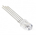
- Tri-Color LED -- Because everyone loves a blinky.
- Red, Blue, Yellow and Green LEDs -- Light-Emitting Diodes make great general indicators.
- Red, Blue, Yellow and Green Tactile Buttons -- Go crazy with different colored buttons.
- 10K Trimpot -- Also known as a variable resistor, this is a device commonly used to control volume and contrast, and makes a great general user control input.
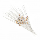
- 330 Ohm Resistors -- Great current-limiting resistors for LEDs, and strong pull-up resistors.
- 10K Ohm Resistors -- These make excellent pull-ups, pull-downs and current limiters.
- SN754410 H-Bridge IC -- This nifty little Integrated Circuit (IC) is perfect for controlling the speed and direction of up to two separate motors.
- 4xAA Battery Holder -- Used to power the RedBoard without being connected to your computer. Sorry! Batteries not included.
Suggested Reading
Before continuing with this guide, we recommend you be somewhat familiar with the concepts in the following tutorials:
- Voltage, Current, Resistance and Ohm's Law -- The most basic concepts in electronics and electrical engineering. Get very familiar with these concepts, as they will be used throughout your electronics adventure.
What is a Circuit? -- In this guide, we will be building a variety of circuits. Understanding what that means is vital to understanding the Inventor's Kit.
How to Use a Breadboard -- First time working with a breadboard? Please check out this tutorial! It will help you understand why the breadboard is great for prototyping and how to use one.
Open Source!
At SparkFun, our engineers and educators have been improving this kit and coming up with new experiments for a long time. We would like to give attribution to Oomlout, since we originally started working off the Arduino Kit material many years ago. Both the Oomlout and SparkFun versions are licensed under the Creative Commons Attribution-ShareAlike 3.0 Unported License.
To view a copy of this license, visit this link or write to: Creative Commons, 171 Second Street, Suite 300, San Francisco, CA 94105, USA.
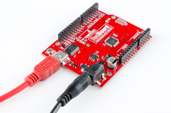
What is the SparkFun RedBoard?

At SparkFun we use many Arduinos, and we’re always looking for the simplest, most stable one. Each board is a bit different, and no one board has everything we want, so we decided to make our own version that combines all our favorite features. The SparkFun RedBoard combines the simplicity of the UNO’s Optiboot bootloader (which is used in the Pro series), the stability of the FTDI (which we all missed after the Duemilanove was discontinued) and the R3 shield compatibility of the latest Arduino UNO R3.
We will be programming the RedBoard over a USB Mini-B cable using the Node.js and Johnny-Five: Just plug in the board after installing Firmata, and you’re ready to run code. The RedBoard has all of the hardware peripherals you know and love: 14 digital I/O pins with 6 PWM pins, 6 analog inputs, UART, SPI and external interrupts. We’ve also broken out the SDA, SCL and IOREF pins that showed up on the UNO R3, so the RedBoard will be compatible with future shields. This version adds an SMD ISP header for use with shields.
You can power the RedBoard over USB or through the barrel jack. The onboard power regulator can handle anything from 7 to 15VDC. Check out the related items below for a compatible wall-wart power supply.
What is Node.js and Johnny-Five?
What is Node.js?
Node.js® is a JavaScript runtime built on Chrome's V8 JavaScript engine. Node.js uses an event-driven, non-blocking I/O model that makes it lightweight and efficient. The Node.js package ecosystem, npm, is the largest ecosystem of open source libraries in the world.
Basically, Node.js is the ability and environment to run JavaScript on the server side (hardware) of a project rather than in a browser. This enables you to interact with things you weren't normally able to, such as the file system, launch processes (programs) or your operating system.
Node.js is super modular, which means that it is made up of a bunch of puzzle pieces called modules. Being so modular is great because it allows you to install the software that you really need, rather than a bunch of stuff that you may or may not use in the end.
Node.js has a huge community of developers who create and use a slew of third-party modules housed in NPM, which is the Node Package Manager. You will be using npm a lot if you are working through this guide; it will be your source of modules to work with a number of APIs and enable you to get different services to talk to your hardware. Speaking of NPM and modules, you will be interacting with your RedBoard by using the Johhny-Five module and installing it through NPM!
What is Johnny-Five?

Johnny-Five is the JavaScript Robotics and IoT Platform. Released by Bocoup in 2012, Johnny-Five is maintained by a community of passionate software developers and hardware engineers. More than 75 developers have made contributions toward building a robust, extensible and composable ecosystem.
Essentially, Johnny-Five (J5) enables JavaScript programmers to develop around embedded development boards such as an Arduino, Raspberry Pi or Tessel 2. Johnny-Five supports more than X different development boards for use in robotics, IoT and other hardware interactions.
J5 is easily installed as a Node.js module and, just like the rest of Node, supports asynchronous programming. This means that it is event-driven, so it reduces latency and "blocking code," which is to say that you no longer have to worry about a certain process taking so long that it blocks another piece of code.
Why JavaScript and Hardware?
With the advent of Node.js, JavaScript no longer just controls the functionality of the web on the user end of things, but also resides on the server, or back end. It doesn't take too much mental strain to extend that logic to small single-board computers and being able to control their inputs and outputs.
The real strength of using JavaScript with hardware falls under the idea that a developer no longer needs to jump from the language of the web to a hardware language such as C or Arduino and make the two talk to one another (not an easy task). If a developer can stay in a single language and even in the same file the whole time, development becomes faster and more streamlined, and the barrier to entry for applications around IoT becomes lower. In fact, the file that you would use to control your hardware and serve a web interface is the same! This guide will highlight this strength. In each experiment there is an Exploring Node.js section where we will extend the experiment with a module that incorporates a higher degree of connectivity and functionality.
The time to Awesome is much, much shorter!
Trying It Out With the Chrome App
To make things easy, there is a Johnny-Five Chrome app that enables you to program your boards using Johnny-Five through a web browser. This is great for people who just want to try it out before installing Node.js on their machine, or schools who are using Chromebooks and want their students to get started in JavaScript-based robotics.
To get started with using the app, sign in to your Google account and navigate to the app store. Search for "johnny-five" or use the button below.
You should be greeted by an app info page that looks like this:
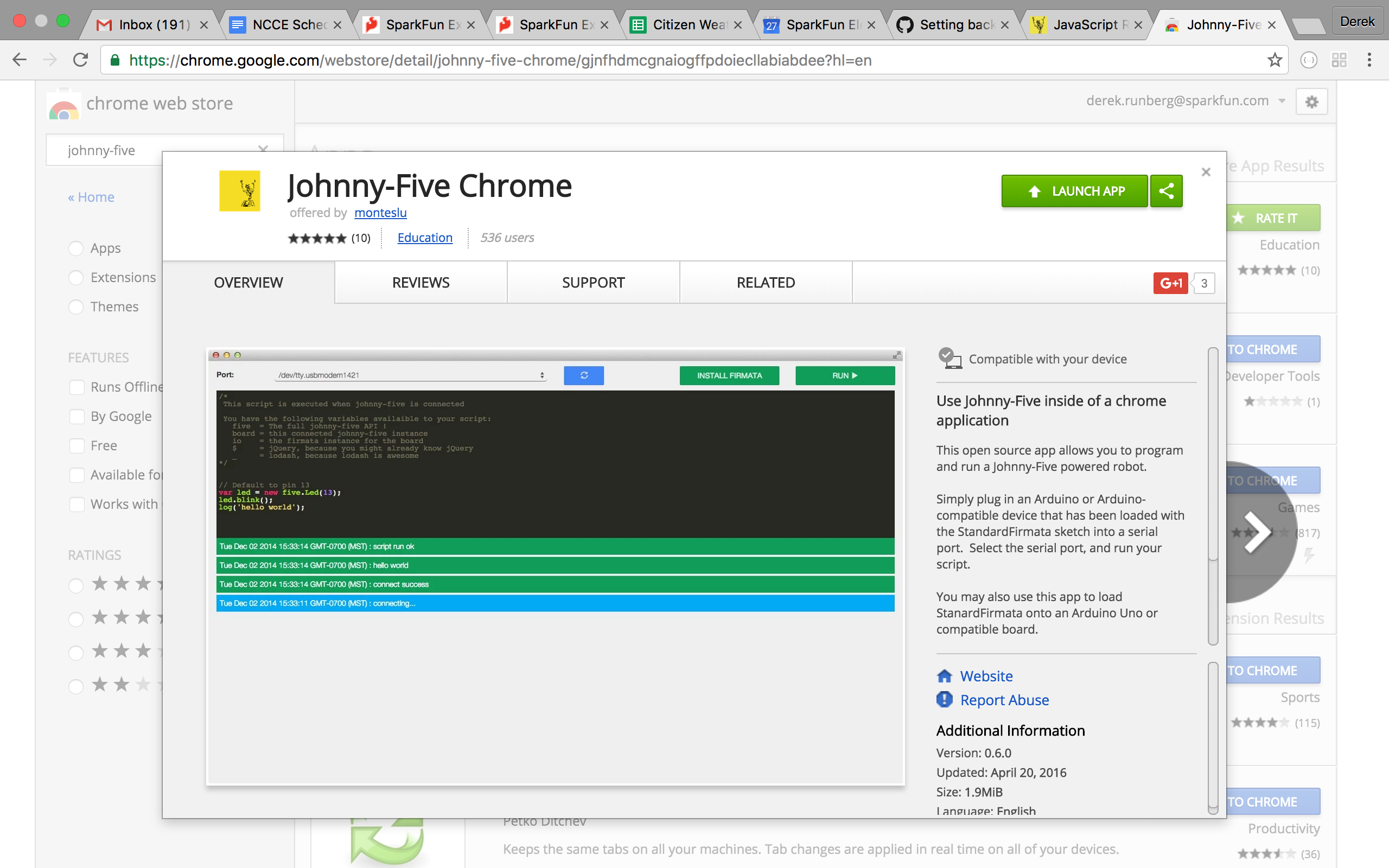
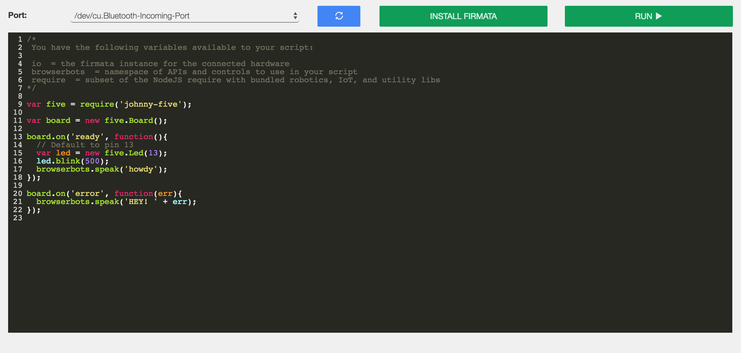
Go ahead and click "Install App." The app will install, and then you can launch it. Upon launching you will see the text editor with some code pre-populated.
Programming in the Cloud
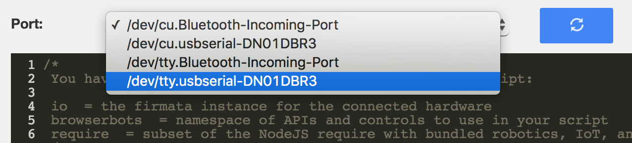
Go ahead and plug your board into your computer using the USB cable. Give your computer a few minutes to detect the board and then from the Port menu select either a "COMXXX" port if you are in a windows machine or a "dev/tty/serialXXXX" if you are on a mac.
With your port selected, you can now install Firmata. Firmata is the firmware that resides on the Arduino and allows Johnny-Five to communicate back and forth with your board. Click "Install Firmata". The app will install Firmata (Patience, this may take a while). Once complete you can now test the board to make sure that everything is up and running.
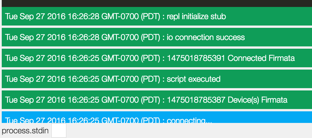
Go ahead and click the "Run" button to run the code that is in the editor window. This will cause the console at the bottom to return some information and the LED on pin 13 to blink on and off pretty quickly.
With that you are ready to go forth and explore the world of JavaScript robotics!
The Catch!
The app is designed with an introduction to JavaScript robotics in mind, in hopes that the user would later install a full development environment on their computer to build more complex projects. The limitation to using the Johnny-Five Chrome App is that you cannot use any other Node.js Modules with it. Which means the Exploring Node.js sections of each Experiment in this guide will only work for those who have Node.js installed on their computers locally and are working in a text editor.Software Installation and Setup
Node.js

Node.js is a JavaScript runtime, that is, it's software that can execute your JavaScript code. Node.js has special features that support some of the best potentials of the JavaScript programming language, like event-driven, non-blocking I/O. npm is Node's package manager. It's a giant repository of encapsulated bits of reusable useful code, called modules, that you can use in your programs. npm will get installed for you when you install Node.js.

Installing Node.js is a straightforward download-and-double-click process. Head on over to the Node.js website. Heads up: You'll want to select the "LTS" version for download (LTS stands for long-term support). At time of writing, LTS is v4.4.5:

Text Editor (Atom)
You will need a text editor in which to edit and save your JavaScript files. This means a plain text editor, not a Word document. If you've already got one, like SublimeText, Notepad++, vim, etc., groovy. If not, go ahead and install Atom.
You can use any text editor you like if you already have on installed and are up and running. But, if you have never used a text editor to write JavaScript, HTML, etc. we recommend using Atom. Atom is a free and open source text editor that works on all three major operating systems, is light weight and when you get comfortable...it's hackable!
Download Atom by heading to the Atom website.
FTDI Drivers
To use the RedBoard or Arduino with Node.js and Johnny-Five you will need FTDI Drivers installed on your computer. We have a tutorial to help walk you through that process. Don't worry we will wait for you to come back before moving on.
How to Install FTDI Drivers
Flashing Firmata
To use Johnny-Five with an Arduino we need to install the Firmata firmware on the board. Firmata is a firmware for microcontrollers that turns the microcontroller into a slave of sorts. It sets it up so that is listening for commands from another device or computer. In essence it allows us to control the Arduino without uploading code and just running it on our computer.
There are two ways to install firmata on your redBoard. These are dependent on whether you have the Arduino IDE installed on your computer or not.
Installing Firmata through Arduino
If you already have Arduino installed you can install Firmata from the examples that come with Arduino. To do this, open your Arduino IDE and plug your board into your computer using a USB cable.
Then in the Arduino IDE at the Tools drop down menu set the board type by selecting the following Tools > Board > Uno.
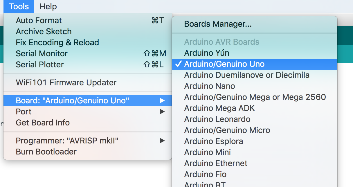
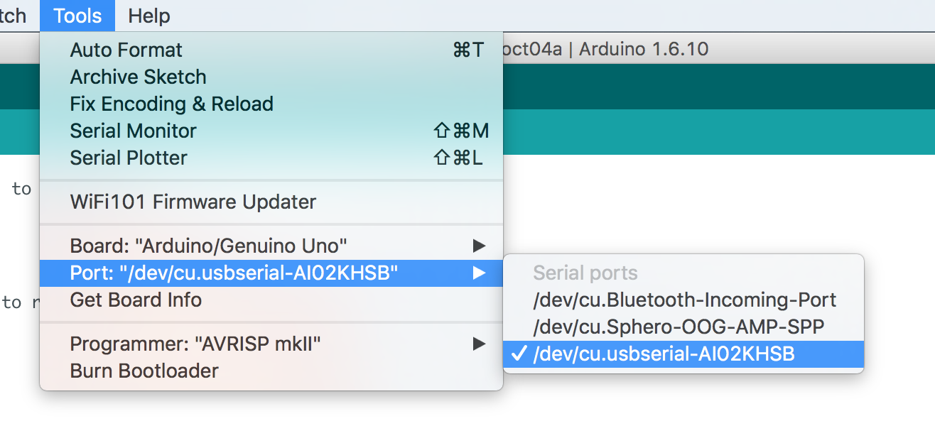
Now, from the Tools menu select your Serial port by selecting the following Tools > Port > COM## The COM## will probably be somewhere in the 3 to 5 range.
Note: Mac users your port list will look different. You are looking for "/dev.cu.usbserial-XXXXX" rather than "COM##"
Now, to open Firmata from the examples folder! Select the following File > Examples > Firmata > standardFirmataPlus
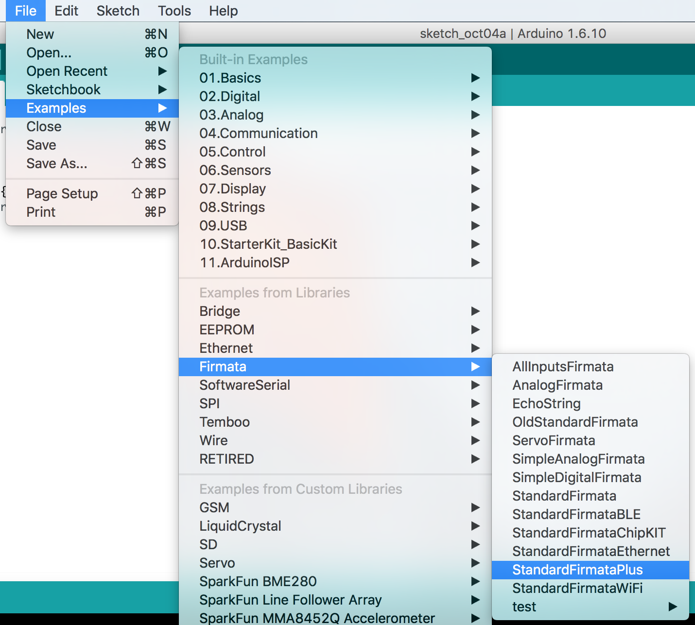
Now click the upload (Arrow button at the top left) to upload Firmata. With that you are done installing Firmata from the Arduino IDE. You can now close Arduino.
Installing Firmata through Interchange
If you have never used Arduino and/or installed the Arduino IDE, there is no point in installing it for a single time use. There is a command line tool that you can use to install Firmata without the fuss of installing Arduino only to use it once and then never use it again (that is if you stick with Node.js)
The command line tool we are talking about is called Interchange and it is designed specifically for this reason.
Installing interchange through npm
To install interchange type the following into your console.
npm install nodebots-interchange -g
Interchange will install with an output that will look somewhat scary to a newcomer of Node.js. It will look like this.
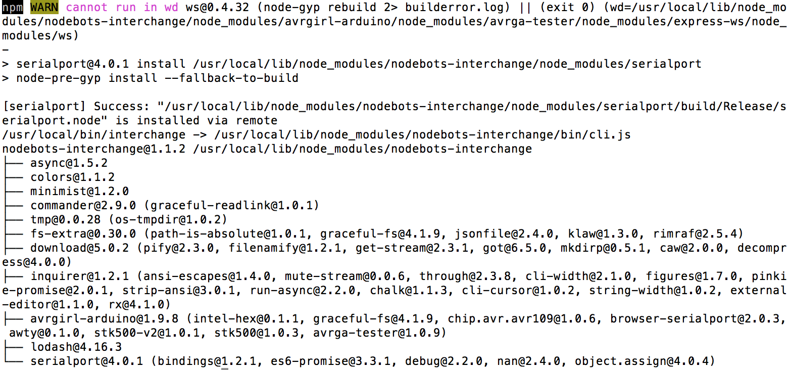
Flashing the RedBoard with Interchange
Now, to install Firmata onto your redboard, plug the board into your computer using a USB cable then type the following command to launch the Interchange tool.
interchange install --interactive
The --interactive flag allows you to use the user interface to select your board and firmware options.
Select your firmware that you would like to install. We want to install Standard Firmata. Select it using your arrow keys.
language:console
 ? Choose a firmware
  node-pixel
  hc-sr04
❯ StandardFirmata
Next select your board. The RedBoard is the same as the Arduino Uno. So, select 'Uno' from the list.
language:console
? Choose a firmware StandardFirmata
? Choose a board
❯ uno
  nano
  pro-mini
Finally, select your port, it should be "COM##" on windows or "/dev/tty/cu.usbserial-XXXX..." on mac.
language:console
? Choose a firmware StandardFirmata
? Choose a board uno
? Choose a port
  /dev/cu.Bluetooth-Incoming-Port
  /dev/cu.Sphero-OOG-AMP-SPP
❯ /dev/cu.usbserial-AI02KHSB
With that Interchange will install firmata for you. You should see the terminal out information similar to this...
language:console
? Choose a firmware StandardFirmata
? Choose a board uno
? Choose a port /dev/cu.usbserial-AI02KHSB
 Retrieving manifest data from GitHub
 Downloading hex file
 connected
 reset complete.
 flashing, please wait...
 flash complete.
Now your RedBoard is ready to be programmed using Johnny-Five and Node.js
Project Directory Setup
When you want to build a Johnny-Five project you want to build a directory for the project. Why? you may ask. Because like any other Javascript project it can scale up to be pretty large using a number of modules and files beyond the basic single file you end up creating in Arduino.
For Example when you install a node module a node_modules directory is created. We want to keep each node_modules directory seperate from your other projects.
Node Projects Directory
From the command line you should navigate to where you would like to store all of your node.js projects. For example I store all of my projects in a directory in my documents folder. Let's do that.
From the command line change directory (cd)to your documents directory. As an example I typed the following.
cd documents
Now create a new directory to store all of your node projects by typing the following.
mkdir node_projects
Once you have created your directory you can now cd into it by typing
cd node_projects
SIK Project Directory
now that you are in your projects folder you will want be creating a project directory for each experiment. You will do this at the beginning of each experiment so that each one will be a standalone project. We highly recommend that you group them all together in one directory. I created one called sik and then navigated into it by typing the following commands.
mkdir sik
cd sik
Experiment 1: Led
Introduction
Note: If you ARE using the Chrome App you will skip any console commands and run the example code directly in the app
LEDs are small, powerful lights that are used in many different applications. To start off, we will work on blinking an LED, the "Hello, World!" of microcontrollers. That's right -- it's as simple as turning a light on and off. It might not seem like much, but establishing this important baseline will give you a solid foundation as we work toward more complex experiments.
Parts Needed
You will need the following parts:
- 1x Breadboard
- 1x SparkFun RedBoard
- 1x LED
- 1x 330Ω Resistor
- 3x Jumper Wires
Didn't Get the Tinker Kit?
If you are conducting this experiment and didn't get the Tinker Kit, we suggest using these parts:


Resistor 330 Ohm 1/6 Watt PTH - 20 pack
COM-11507
Suggested Reading
Before continuing with this experiment, we recommend you be familiar with the concepts in the following tutorial:
- Light-Emitting Diodes -- Learn more about LEDs!
Introducing the LED
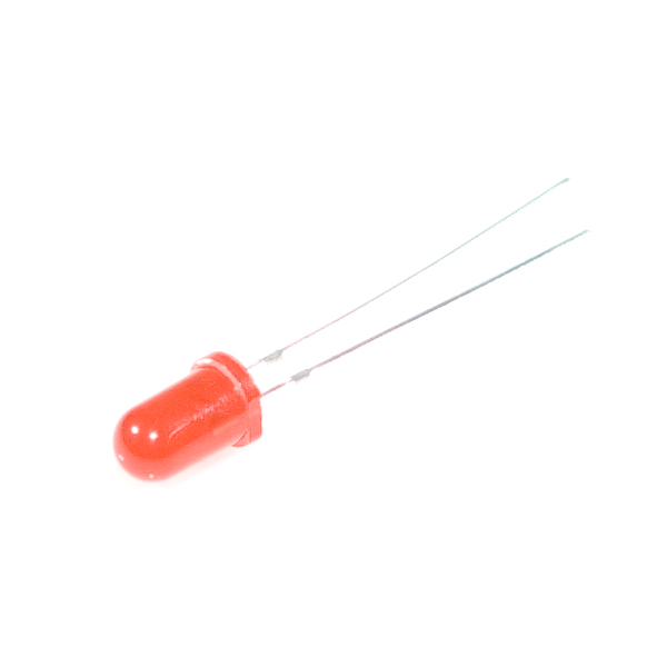
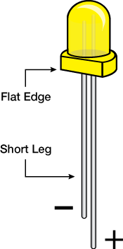
A Light-Emitting Diode (LED) will only let current through it in one direction. Think of an LED as a one-way street. When current flows through the LED, it lights up! When you are looking at the LED, you will notice that its legs are different lengths. The long leg, the "anode," is where current enters the LED. This pin should always be connected to the current source. The shorter leg, the "cathode," is the current’s exit. The short leg should always be connected to a pathway to ground.
LEDs are finicky when it comes to how much current you apply to them. Too much current can lead to a burnt-out LED. To restrict the amount of current that passes through the LED, we use a resistor in line with the power source and the LED's long leg; this is called a current-limiting resistor. With the RedBoard, you should use a 330 Ohm resistor. We have included a baggy of them in the kit just for this reason!
Hardware Hookup
Ready to start hooking everything up? Check out the wiring diagram and hookup table below to see how everything is connected.
| Polarized Components | Pay special attention to the component’s markings indicating how to place it on the breadboard. Polarized components can only be connected to a circuit in one direction. |
**Please note: Pay close attention to the LED. The negative side of the LED is the short leg, marked with a flat edge. **
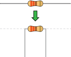
Components like resistors need to have their legs bent into 90° angles in order to correctly fit the breadboard sockets. You can also cut the legs shorter to make them easier to work with on the breadboard.
Wiring Diagram for the Experiment

Writing Your First Script
Now that your circuit is built, let's dive into the software side of things!
First off, lets create a project directory for this experiment inside of your sik directory that you created in the software setup section. Once you are in the sik directory create a new project directory, initiate an npm project and install Johhny-Five by typing the following commands.
mkdir exp_01;
cd exp_01;
npm init -y;
npm install johnny-five
With that you can now create a JavaScript file by typing the following command.
touch blink.js
Now open your blink.js file in your text editor and type out or copy and paste the following code.
language:javascript
const five = require('johnny-five');

const board = new five.Board();

board.on('ready', ()=>{
   const led = new five.Led(13);

   led.blink(500);
});
Once you have everything there, make sure you save your file. Run this script from the command line by typing the following command.
node blink.js
What You Should See
You should see your LED blink on and off. If it doesn't, make sure you have assembled the circuit correctly and verified and uploaded the code to your board, or see the Troubleshooting section.
Your console should also output a bunch of information about the board connecting, etc. It should look similar to this!
language:console
1475709038686 Device(s) /dev/cu.usbserial-DN01DHUL
1475709038699 Connected /dev/cu.usbserial-DN01DHUL
1475709042013 Repl Initialized
>>
Code to Note
language:javascript
const five = require('johnny-five');
Node.js is super modular! Which is a good thing, you only add the functionality that you really need. You add functionality by installing modules (as you did earlier) and then requiring them in your script. This is how we use the require() function to add Johnny-Five to our script as a five object.
language:javascript
const board = new five.Board()`
When you look down at your desk, you have a bunch of parts. One of them is a board. The great thing about programming hardware in JavaScript is that almost every piece of hardware you use is defined as an object. We define our "board" as a new five.Board(). Whenever you define an object in Johnny-Five for the first time it will be a new object; in this case, a Board object.
language:javascript
board.on('ready', ()=>{
   //do stuff
});
We have defined our board and now we have its first method. This method is special because it is called an "event listener". An event listener lies in wait listening for an event to happen. In this case it is they "ready" event. The "ready" event happens once the Firmata firmware on the board is finished setting up and is "ready" to accept commands. An event listener has what is called a callback function. A callback is a function that is triggered when the function is complete. In this case, with an event listener, when it receives a message.
language:javascript
const led = new five.Led(13);
Again, if you look down at your circuit, you are using an LED. There is an object for that. Inside of our board event listener we create a new Led object and pass it the pin number we are using, pin 13 in this case.
language:javascript
led.blink(500);
We can now use the led object to control the LED. For this example we used the blink() method and passed it the blink interval in milliseconds (500).
Troubleshooting
Error Return From Node.js
Make sure that you aren't missing any semicolons, commas or parenthesis. spelling and syntax matters in javascript!
Connection Timeout
Make sure that you have installed Firmata correctly on your RedBoard. Try using Interchange to go through the installation process one more time.
Led Not Blinking
Make sure that you built the circuit correctly! The LED is polarized and only works in one direction. Also, check your wiring on the breadboard, it is easy miss a row of pins!
Still No Success
A broken circuit is no fun. Send us an email, and we will get back to you as soon as we can: techsupport@sparkfun.com
Beyond Blink
The Led class has so much more to offer than just the blink() method. Here are a couple of other methods that are available to you to use with your Led object. We have included a few code snippets to play around with before moving on to Experiment 2.
On and Off
If you are looking to just turn your LED on or off there are methods for that and they make it super easy!
Here is an example of using the on() and off() methods to turn the LED on for 5 seconds when the board is ready and then off.
From your console create a new file called on_off.js by typing the following command.
touch on_off.js
Now open your on_off.js file with your text editor and type out or copy and paste the following code.
language:javascript
const five = require('johnny-five');

const board = new five.Board();

board.on('ready', ()=>{
   const led = new five.Led(13);

   led.on();
   board.wait(5000, ()=>{
      led.off();
   });
});
Make sure you save the file and then run the code with the following command.
node on_off.js
Your LED should turn on for 5 seconds and then turn off.
Notice that we also used an interesting method from the Board class... wait(). The wait() method allows us to stop what is going on for a given amount of time, and then when that time is up call a callback. A callback is a function that is called by certain methods when they are finished. The callback is one of the core pieces of asynchronous code.
Toggle
Toggle is pretty much what it states. It takes the state of the LED (on or off) and flips it to the other state.
From your console create a new file called toggle.js by typing the following command.
touch toggle.js
Now open your toggle.js file with your text editor and type out or copy and paste the following code.
language:javascript
const five = require('johnny-five');

const board = new five.Board();

board.on('ready', ()=>{
   const led = new five.Led(13);

   led.on();
   board.loop(1000, ()=>{
      led.toggle();
   });
});
Make sure you save the file and then run the code with the following command.
node toggle.js
Your LED should be blinking once per second.
Again, we use another Board method to control the timing of things here. This method is called loop(). The loop() method accepts two arguments. The first is the timing of the loop in milliseconds. In our example code we have it set to 1000ms (1 second), so it will repeat once per second. The second argument is a callback. Like in the previous section a callback is a function that is called when that function is complete. In this case that function only has a single line of code and that is the led.toggle();. So, every second the LED state is toggled and the LED should blink once per second.
Exploring Node.js
For every experiment in this guide this section will cover how you can bring in other modules both core modules from Node.js itself or other 3rd party modules to do cool things from posting data to the Internet, creating your own console menu system or creating files on your own computer. We will tie these newly found modules to the hardware you learn about to build interactive projects that will create a toolbox for you to explore the Internet of Things.
Experiment 2: Sensor
Introduction
Note: If you ARE using the Chrome App you will skip any console commands and run the example code directly in the app
In this circuit you will work with a potentiometer. You will learn how to use a potentiometer to control the timing of a blinking LED by reading a sensor and storing it as a variable, then using it as your delay timing.
Parts Needed
You will need the following parts:
- 1x Breadboard
- 1x SparkFun RedBoard
- 1x LED
- 1x 330Ω Resistor
- 7x Jumper Wires
- 1x Potentiometer
Didn't Get the Tinker Kit?
If you are conducting this experiment and didn't get the Tinker Kit, we suggest using these parts:

Resistor 330 Ohm 1/6 Watt PTH - 20 pack
COM-11507
Suggested Reading
Before continuing with this experiment, we recommend you be familiar with the concepts in the following tutorial:
Introducing the Potentiometer
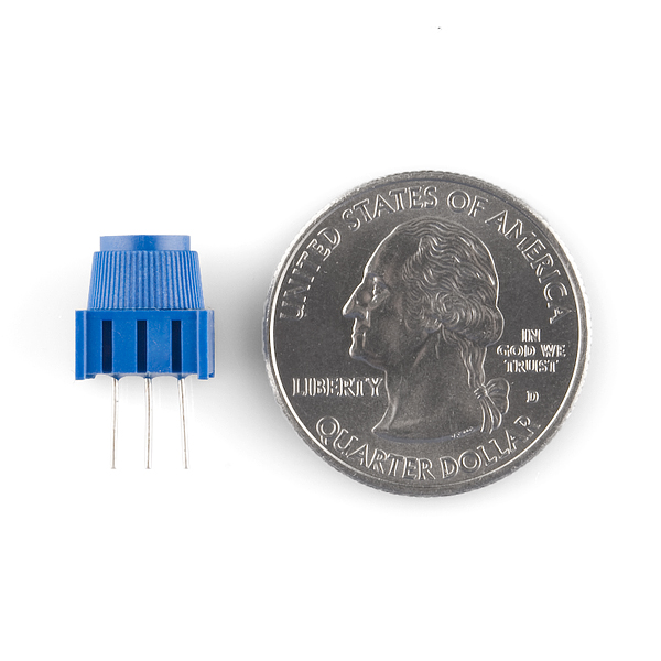
A potentiometer is a resistance-based analog sensor that changes its internal resistance based on the rotation of its knob. The potentiometer has an internal voltage divider enabling you to read the change in voltage on the center pin with a microcontroller (the RedBoard). To hook up the potentiometer, attach the two outside pins to a supply voltage (5V in this circuit) and ground. It doesn’t matter which is connected where, as long as one is connected to power, and the other to ground. The center pin is then connected to an analog input pin so the RedBoard can measure the change in voltage. When you twist the knob, the sensor reading will change!
Hardware Hookup
Ready to start hooking everything up? Check out the wiring diagram and hookup table below to see how everything is connected.
| Polarized Components | Pay special attention to the component’s markings indicating how to place it on the breadboard. Polarized components can only be connected to a circuit in one direction. |
Wiring Diagram for the Experiment

Reading the Sensor Values
Remember to Setup Your Project Directory!
From your `SIK` directory make sure that create a new project directory for this experiment and create an empty project by typing in the following commands while in your `SIK` directory.
mkdir exp_02;cd exp_02;
npm init -y;
npm install johnny-five
Once done you will have created a project directory, moved into it, created an npm project and installed Johnny-Five. Wahoo!
language:javascript
const five = require('johnny-five');

const board = new five.Board();

board.on('ready', ()=>{
   const sensor = new five.Sensor('A0');

   sensor.on('data', ()=>{
      var val = sensor.value;
      console.log('Sensor Value: ',val);
   });
});
Make sure you save your file and then run your script by typing the following command in your terminal.
node sensor.js
What You Should See
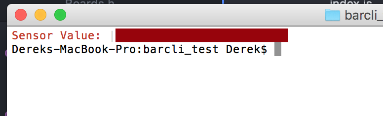
You shouldn't see anything happening physically on your board, but your terminal should start printing out information every 200 milliseconds (really fast!). This data should look something like this.
language:console
Sensor Value: 324
Sensor Value: 350
Sensor Value: 500
Sensor Value: 526
Sensor Value: 627
Sensor Value: 627
...
Code to Note
language:javascript
const sensor = new five.Sensor('A0');
Just like the Led object, we also have to create a Sensor object using the new constructor. With the Sensor object we pass it what pin it is attached to as a String, in this case since we are using an analog pin that is "A0".
language:javascript
sensor.on('data', ()=>{
   //do something cool!
});
The Sensor object has an event listener similar to the Board object. But, instead of listening for "ready" it is listening for either "data" or "change". The "data" event fires at a constant rate which you will explore more in Experiment 5. The "change" event is fired every time that the sensor value actually changes. So, if the potentiometer doesn't change and the value stays the same, the event doesn't happen.
The second part of the event listener is a callback function that is executed when the event is triggered.
language:javascript
var val = sensor.value;
When the event is triggered we can capture the sensor value by storing it in a variable. This variable (val) is a local variable, which means that it can only be used within the event callback function and nowhere else.
language:javascript
console.log("Sensor Value: ", val);
To view the variable value of val we log it to the console and concatenate it with the string of "Sensor Value: " to give more context to it.
Controlling Blink
But wait, there is an LED on our breadboard! Yep, you are right. Let's see how we can use the potentiometer and its value to change the interval of the blink() method.
Let's create a new javascript file and name it "sensor_led.js" by typing the following command.
touch sensor_led
Now open your sensor_led.js file and type out, or copy and paste the following script.
language:javascript
const five = require('johnny-five');

const board = new five.Board();

board.on('ready', ()=>{
   const sensor = new five.Sensor('A0');
   const led = new five.Led(13);

   sensor.on('change', ()=>{
      var interval = sensor.value;
      led.blink(interval);
   });
});
Once you are done, make sure to save the file and then run it with the following command in your terminal.
node sensor_led.js
Once you see the terminal run the code go ahead and twist the potentiometer and you should see something like this.
Troubleshooting
Getting Random Values
Make sure that you have wired the sensor up correctly and wired it to the pin you specified in your code, you may be reading the wrong pin
Getting only 0 or 1023
Check your circuit, you may have your analog pin wired directly to either ground or 5V
Cannot Find ...
If you get an error about not being able to find Johnny-Five or any other module make sure that you have installed them in your project using NPM!
Still No Success
A broken circuit is no fun. Send us an email, and we will get back to you as soon as we can: techsupport@sparkfun.com
Beyond Value
The Sensor object has a lot more to offer than a value and an event listener. Here are a few methods and some code snippets that may be helpful to you as you explore the Sensor class a bit more.
Scale
The value attribute gives us a number range that is 0-1203 which unless you are doing something in base 10 counting, seems pretty arbitrary. What if we want to deal with a sensor value in percentage (0-100%)? Enter the scale() method. The scale method takes the sensor value and scales it to a range of your choosing. Try this out...
Create a new file and name it "scale_sensor.js" by using the following command.
touch scale_sensor.js
Now, open your scale_sensor.js file in a text editor and type out or copy and paste the following code.
language:javascript
const five = require('johnny-five);

const board = new five.Board();

board.on('ready', ()=>{
   const sensor = new five.Sensor('A0');

   sensor.on('change', ()=>{
      var scaleVal = sensor.scaleTo(0,100);
      console.log('Scaled Value: ', scaleVal);
   });
});
Make sure you save and then run the script using the following command.
node scale_sensor.js
Once this runs it will log your scaled values to the console as shown here.
language:console
Scaled Value: 0
Scaled Value: 23
Scaled Value: 42
Scaled Value: 37
Scaled Value: 47
Scaled Value: 32
...
Within
The Sensor object also has the within() method. This method accepts two arguments. The first is the range that you are looking for the value to be within as an array of two numbers. Example: [100,1000]. The second argument is a callback function that is triggered when the sensor value falls with that range. Let's check it out in action using the LED!
Create a new javascript file called sensor_within.js using the following command.
touch sensor_within.js
Now open the new file in a test editor and type out or copy and paste the following code.
language:javascript
const five = require('johnny-five');
const board = new five.Board();

board.on('ready', ()=>{
   const sensor = new five.Sensor('A0');
   const led = new five.Led(13);

   sensor.on('data', ()=>{
      sensor.within([200,400], ()=>{
      led.on();
      });
      led.off();
   });
});
Make sure you save this file and then you can run it with the following command.
node sensor_within.js
Once your code runs turn your potentiometer and the LED will turn on at a certain point (when it enters the within range) and then turn off again when it exits that range.
Exploring Node.js
Just spitting numbers out through console.log() isn't the greatest practice and is just plain hard to read. What you really want is some sort of real-time bar graph so you can get a more visual reference without having to read all of those numbers. Fear not! Enter Barcli!
Barcli

Barcli is a simple tool for displaying real time data in the console. Multiple instances of barcli can be stacked to show multiple axes, sensors or other data sources in an easy to read horizontal bar graph. Barcli exists because I needed a way to visualize Johnny-Five sensor data quickly and easily. console.log is hard to read, especially if you have more than one datapoint to track.
So, how do we use barcli? Lets take a look!
First of all we need to install the Barcli module through npm. We do this by typing the following command into the console. (Make sure that you are still in your exp_2 project directory).
npm install barcli
This should install barcli locally and you should get an output similar to this in your console.
language:console
npm WARN package.json barcli_test@1.0.0 No description
npm WARN package.json barcli_test@1.0.0 No repository field.
npm WARN package.json barcli_test@1.0.0 No README data
barcli@0.0.23 node_modules/barcli
└── chalk@1.1.3 (escape-string-regexp@1.0.5, ansi-styles@2.2.1, supports-color@2.0.0, has-ansi@2.0.0, strip-ansi@3.0.1)
Don't worry about the package.json warnings, they are just reminders that there are things missing in your package.json file if you ever wanted to publish this project.
Now, create a new javascript file to use to test barcli out in. Do this by typing the following into your console.
touch barcli_sensor.js
Now open your barcli_sensor.js file with your text editor and type or cut and paste the following code into your empty file.
language:javascript
const five = require('johnny-five);
const barcli = require('barcli');

const board = new five.Board();

const graph = new barcli({
   label: 'Sensor Value',
   range: [0,1023]
   });

board.on('ready', ()=>{
   const sensor = new five.Sensor('A0');

   sensor.on('change', ()=>{
      var val = sensor.value;
      graph.update(val);
   });
});
Make sure you save your file and then run it with the following command.
node barcli_sensor.js
Once your code starts to run you should see a bargraph in your console. Go ahead and turn your potentiometer and see what happens!
The graph moves in real time! pretty cool, huh? Now, if you ever want a more visual feedback for a sensor or any other variable when using Node.js you have a way to graph it!
You can learn more about how to use Barcli on its NPM page.
Experiment 3: LEDs
Introduction
Note: If you ARE using the Chrome App you will skip any console commands and run the example code directly in the app
Now that you've gotten your LED to blink on and off, it's time to up the stakes a little bit – by connecting six LEDs at once. We'll also give your RedBoard a little test by creating various lighting sequences.
Along with controlling the LEDs, you’ll learn a few programming tricks that keep your code neat and tidy!
You will need the following parts:
- 1x Breadboard
- 1x SparkFun RedBoard
- 6x LEDs
- 6x 330Ω Resistors
- 7x Jumper Wires
Didn't Get the Tinker Kit?
If you are conducting this experiment and didn't get the Tinker Kit, we suggest using these parts:
Resistor 330 Ohm 1/6 Watt PTH - 20 pack
COM-11507
Hardware Hookup
Ready to start hooking everything up? Check out the wiring diagram and hookup table below to see how everything is connected.
| Polarized Components | Pay special attention to the component’s markings indicating how to place it on the breadboard. Polarized components can only be connected to a circuit in one direction. |
Wiring Diagram for the Experiment

Writing the Script
Remember to Setup Your Project Directory!
From your `SIK` directory make sure that create a new project directory for this experiment and create an empty project by typing in the following commands while in your `SIK` directory.
mkdir exp_03;cd exp_03;
npm init -y;
npm install johnny-five
Once done you will have created a project directory, moved into it, created an npm project and installed Johnny-Five. Wahoo!
Create a new javascript file called "multiBlink.js" with the following command.
touch multiBlink.js
Now, open your multiBlink.js file with your text editor and type out or copy and paste the following code.
language:javascript
const five = require('johnny-five');

const board = new five.Board();

board.on('ready', ()=>{
    const leds = new five.Leds([4,5,6,7,8,9]);

    board.loop(1000,()=>{
    for(var x = 0; x <= leds.length-1; x++){
    leds[x].on();
    }
    leds.off();
    });
});
Code to Note
language:javascript
const leds = new five.Leds([4,5,6,7,8,9]);
When creating a plural object, or an object that groups a bunch of components (such as the Leds object) you pass the pin numbers as an array.
language:javascript
for(var x = 0; x <= leds.length-1; x++){
    leds[x].on();
    }
We use a for() loop to iterate through the array of leds starting with 0 (the first led in the array) and work our way to the last Led, which happens to be the length of the array minus one. I know it's odd, but when you count 0 as the first spot the length of the array is off by one when we use it in this way.
language:javascript
leds[x].on();
To reference a single led in the array you can specify it by its index. Instead of x this could be 0 for the first led in the array, or 3 for the fourth led.
What You Should See
This is similar to Experiment 1, but instead of one LED, you should see all the LEDs blink. If they don't, make sure you have assembled the circuit correctly and verified and uploaded the code to your board, or see the Troubleshooting section.

Troubleshooting
One LED is not working
Make sure that you check the direction of the LED!
Still not working!
Sometimes its best to take things apart and rebuild! There are a lot of wires and components, there may be a faulty jumper wire or LED, try replacing them
Still No Success
A broken circuit is no fun. Send us an email, and we will get back to you as soon as we can: techsupport@sparkfun.com
Exploring Node.js
You have a huge input at your finger tips! Your keyboard. We take it for granted every day. When you stop and think about it, the amount of information we input into our computers through the keyboard and mouse is astounding.
We can capitalize on your keyboard as an input in Node.js with the keypress module! Install the keypress module with the following command.
npm install keypress
Using keys as an input
Make any Node ReadableStream emit "keypress" events
With your LEDs in a line it makes sense to control how many are lit up in a line with your arrow keys. Every time you press the UP key we want to turn on an LED and every time you press the DOWN key we want to subtract or turn off one of the LEDs.
Let's create a new javascript file and try this out. Create a new file by typing the following command into your console.
touch leds_key.js
Now, open up your new leds_key.js file and type out or copy and paste the following code.
language:javascript
const five = require('johnny-five');
const keypress = require('keypress');

const board = new five.Board();

keypress(process.stdin);

board.on('ready', ()=>{

  const leds = new five.Leds([4,5,6,7,8,9]);

  var index= -1;
  console.log('Press the Up and Down arrow keys!');
  // listen for the "keypress" event
  process.stdin.on('keypress', function (ch, key) {
    console.log(key.name);
    if (key && key.ctrl && key.name == 'c') {
      process.stdin.pause();
    }

    if(key.name == 'up'){
      index++;
    }
    else if(key.name == 'down'){
      index--;
    }

    if(index > 6){
      index = 6;
    }

    if(index < -1){
      index = -1;
    }

    leds[index].toggle();
    });
  });

  process.stdin.setRawMode(true);
  process.stdin.resume();
Make sure that you have saved your file. Once you do go ahead and run this script from the console by typing the following command.
node leds_key.js
Once the script starts you should be prompted by the console to press the up and down arrow keys on your keyboard. When you press the up arrow the LEDs will start to light up as a bar graph. When you press the down key the bar graph should get shorted as leds turn off as shown in the video. Sweet!
You can learn more about the keypress module and how to use it beyond this example at its NPM page.
Experiment 4: Button
Introduction
Note: If you ARE using the Chrome App you will skip any console commands and run the example code directly in the app
Up until now, we’ve focused mostly on outputs. Now we’re going to go to the other end of the spectrum and play around with inputs. In Experiment 2, we used an analog input to read the potentiometer. In this experiment, we’ll be reading one of the most common and simple inputs – a push button – by using a digital input. We will use it to control leds.
Parts Needed
You will need the following parts:
- 1x Breadboard
- 1x SparkFun RedBoard
- 1x RGB LED
- 3x 330Ω Resistor
- 8x Jumper Wires
- 1x Push Button
- 1x 10K Resistors
Didn't Get the Tinker Kit?
If you are conducting this experiment and didn't get the Tinker Kit, we suggest using these parts:
Resistor 330 Ohm 1/6 Watt PTH - 20 pack
COM-11507Suggested Reading
Before continuing with this experiment, we recommend you be somewhat familiar with the concepts in these tutorials:
Introducing the Push Button
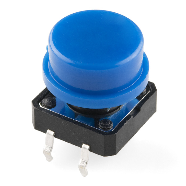
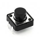
A momentary push button closes or completes the circuit only while it is being pressed. The button has four pins, which are broken out into two sets of two pins. When you press down on the button and get a nice "click," the button bridges the two sets of pins and allows current to flow through the circuit.
How do you know which pins are paired up? The buttons included in this kit will only fit across the breadboard ditch in one direction. Once you get the button pressed firmly into the breadboard (across the ditch), the pins are horizontally paired. The pins toward the top of the breadboard are connected, and the pins toward the button of the breadboard are connected.
Hardware Hookup
Ready to start hooking everything up? Check out the wiring diagram and hookup table below to see how everything is connected.
| Polarized Components | Pay special attention to the component’s markings indicating how to place it on the breadboard. Polarized components can only be connected to a circuit in one direction. |
Wiring Diagram for the Experiment

Digital Input
Previously we've used the analog pins for input; now we'll use the digital pins for input as well. Because digital pins only know about high (on) and low (off) signals, they're perfect for interfacing to pushbuttons and switches that also only have "on" and "off" states.
We'll connect one side of the pushbutton to ground, and the other side to a digital pin. When we press down on the pushbutton, the pin will be connected to ground, and therefore will be read as a low signal by the RedBoard.
But wait -- what happens when you're not pushing the button? In this state, the pin is disconnected from everything, which we call "floating." What will the pin read as, then -- HIGH or LOW? It's hard to say, because there's no solid connection to either 5V or ground. The pin could read as either one.
To deal with this issue, we'll connect a small (10K, or 10,000 Ohm) resistance between the signal pin and 5V. This "pull-up" resistor will ensure that when you're NOT pushing the button, the pin will still have a weak connection to 5 volts, and therefore read as HIGH.
Write the Script
Remember to Setup Your Project Directory!
From your `SIK` directory make sure that create a new project directory for this experiment and create an empty project by typing in the following commands while in your `SIK` directory.
mkdir exp_04;cd exp_04;
npm init -y;
npm install johnny-five
Once done you will have created a project directory, moved into it, created an npm project and installed Johnny-Five. Wahoo!
Create a new javascript file called "button.js" with the following command.
touch button.js
Now, open your button.js file in your text editor and either type out or copy and paste the following code.
language:javascript
const five = require('johnny-five');

const board = new five.Board();

board.on('ready', ()=>{

   const button = new five.Button({
      pin: 10,
      isPullup: false,
      holdtime: 500,
      invert: true
      });
   button.on('press', ()=>{
      console.log('The button is pressed');
   });

   button.on('release', ()=>{
      console.log('the button is released');
   });

   button.on('hold', ()=>{
      console.log('The button is being held down!'
   });
});
Code to Note
language:javascript
const button = new five.Button({
      pin: 10,
      isPullup: false,
      holdtime: 500,
      invert:true
      });
The button object is created like any other Johnny-Five object class, but this time there is a bit more information that goes along with it. Instead of just a pin number we pass it an object of information that includes the pin number, if the pin is internally pulled up and also how long we would like to set holdtime, which is what it says, how long are we defining a "hold" event. The final property is invert, which means that it will flip the logic of the circuit. Since we are pulling the input pin up This information being passed is called the objects shape; it defines the object more than just a pin number.
language:javascript
button.on('press', ()=>{
      //do something cool!
   });
The button object has three different event listeners attached to it. You can set your code to listen for a button "press" event, a "release" event or a "hold" event. These event listeners can all be present in your code as we demonstrated in this example which allows you more freedom of choice as how you can use a button and what happens in each individual callback.
What You Should See
You should see the LED turn on if you press either button, and off if you press both buttons. (See the code to find out why!) If it isn't working, make sure you have assembled the circuit correctly and verified and uploaded the code to your board, or see the Troubleshooting section.
language:console
 The button is pressed
 The button is released
 The button is pressed
 The button is released
 The button is being held down!
 ....
Input to Output
A console log is a great thing, but in the end we want to be able to control a physical thing with a button press, release or hold. You probably noticed that there is an RGB Led in the circuit that we did not use in this first script. Let's take a look at a simple example that leverages the event listeners attached to the button object and control the RGB Led.
First off, let's create a new javascript file and name it "button_rgb.js" from the console using the following command.
touch button_rgb.js
Now open your empty button_leds.js file with your text editor and type or copy and paste the following code.
language:javascript
const five = require('johnny-five');

const board = new five.Board();

board.on('ready', ()=>{
   const rgb = new five.Leds([9,10,11]);
   const button = new five.Button({
      pin: 10,
      isPullup: false,
      holdtime: 500,
      invert: true
     });

   button.on('press', ()=>{
      rgb[1].on();
   });

   button.on('release', ()=>{
      rgb[1].off();
   });

   button.on('hold', ()=>{
      rgb[2].blink(100);
      }
   });
});
Make sure you save your file and then run it from the console by entering the following command.
node button_rgb.js
What You Should See
You shouldn't see anything at first. Go ahead and press the button, then release it. When you press the button one color of RGB should turn on. When you release the button it should turn off. If you hold the button down for longer that half of a second you should see a different color blink at 100ms.
Troubleshooting
Logic is backawards
Are you getting a pushed event when you aren't pressing anything? You have your LED pulled up or down opposite of the logic in your code. set your `invert` property to the opposite of what you currently have
Intermitent button presses
You have a floating signal which means your button circuit is not pulled up or pulled down. You need to wire your signal pin to Ground or 5V with a 10k Ohm resistor
Still No Success
A broken circuit is no fun. Send us an email, and we will get back to you as soon as we can: techsupport@sparkfun.com
Exploring Node.js
Controlling LEDs are all good, but what about other things?
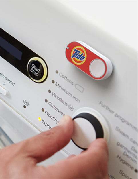
We all have seen the Amazon Dash Button that allows you to order something from Amazon at the press of a button. Well, let's take a look at how we can build something similar... a takeout button that sends a text message to someone to see if they would pick up takeout for you. Are ready to be lazy? Yeah, me too! Let's pull on the elastic banded pajama pants, laze on the couch and press a button!
IFTTT Takeout? Button
NodeJS module that will connect with the IFTTT maker channel
If you have never heard of the wonderful service called If This Than That you are missing out. IFTTT makes interconnecting your online services (Twitter,email, google docs, your phone, etc) to each other to simplify your life through automation. It has also become one of the leading platforms for developing IoT services as well. We are going to write a script that will text a friend, spouse, significant other to grab some takeout on their way home.
Setting up IFTTT
First off, you need to create an account with IFTTT. Go ahead and go here and sign up for IFTTT. Don't worry it's free!
Once you have signed up for an account click on "My Recipees" at the top of your window and then click "Create Recipe".

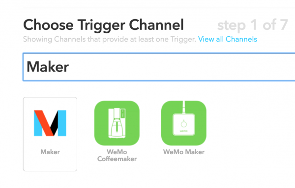
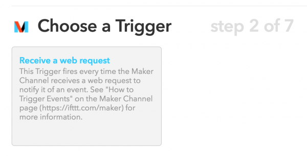
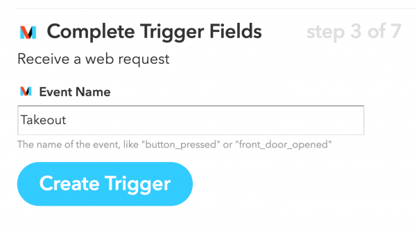
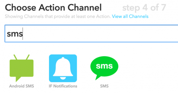
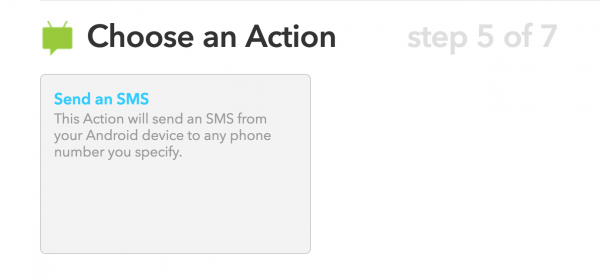
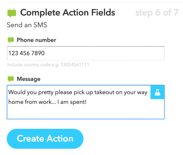
From here, search for "Maker" channel and follow the screen captures below to create a recipe for sending a text message (Android) to someone when a Maker event is triggered.


Node.js Code
Now that you have a recipe, it's time to write some code to make it all work with the original button circuit you built.
But, before we dive into knocking out code, we need to install the IFTTT Maker Channel module for Node.js. In your project directory for this experiment type the following command to install the module.
npm install npm i node-ifttt-maker
Now, once that is complete create a new javascript file called "takeout.js" with the following command.
touch takeout.js
Now open your takeout.js file with a text editor and type or copy and paste the following code into it.
language:javascript
const five = require('johnny-five');
const ifttt = require('node-ifttt-maker');

const board = new five.Board();
const takeout = new ifttt('<Your Maker Key>');


board.on('ready', ()=>{
   const button = new five.Button({
      pin: 10,
      isPullup: false,
      holdtime: 500
      }
    });

   button.on('hold', ()=>{
      takeout.request({event: 'takeout',method: 'GET'}, (error)=>{
      if(error){
          console.log(error);
          }
          else{
      console.log('message sent');
      }
      });
   });
});
Few! That's a lot of code! Notice that the ifttt object needs a Maker Key from you. To get your maker key go to https://ifttt.com/maker while you are logged in and it should bring up your maker dashboard with your key on it. Copy and paste that key into your code as a string (inside of quotes).
Now, make sure your code is saved and run your project from the console by typing the following.
node takeout.js
Once the project starts up, you should be able to press and hold the button for at least half a second and then it will send a text message to the phone number you entered into your recipe.
Now, sit back, pick your favorite movie and wait for the General Tzao to show up!
If you want to explore the node-ifttt-maker module a bit more you can find out more about it on its NPM page.
Experiment 5: Sensor (With Shape)
Introduction
In Experiment 2, you got to use a potentiometer, which varies resistance based on the twisting of a knob and, in turn, changes the voltage being read by the analog input pin. In this circuit you’ll be using a photoresistor, which changes resistance based on how much light the sensor receives. You will read the light value of the room and have an LED turn on if it is dark and turn off if it is bright. That's right; you are going to build a night light!
Parts Needed
You will need the following parts:
- 1x Breadboard
- 1x SparkFun RedBoard
- 1x LED
- 1x 330Ω Resistor
- 7x Jumper Wires
- 1x Photoresistor
- 1x 10K Resistor
Didn't Get the Tinker Kit?
If you are conducting this experiment and didn't get the Tinker Kit, we suggest using these parts:

Resistor 330 Ohm 1/6 Watt PTH - 20 pack
COM-11507
Introducing the Photoresistor
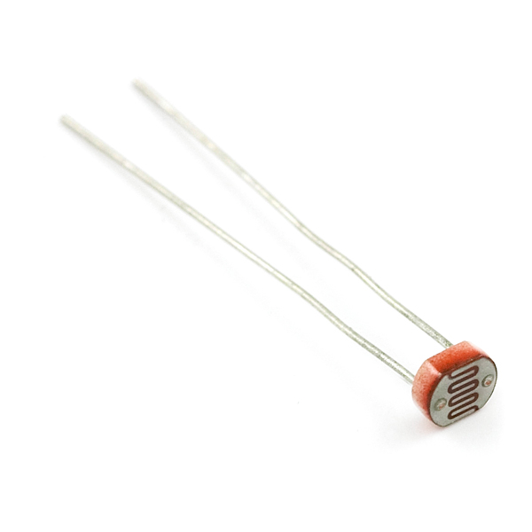
The photoresistor changes its resistance based on the light to which it is exposed. To use this with the RedBoard, you will need to build a voltage divider with a 10K Ohm resistor as shown in the wiring diagram for this experiment. The 101 board cannot read a change in resistance, only a change in voltage. A voltage divider allows you to translate a change in resistance to a corresponding voltage value.
The voltage divider enables the use of resistance-based sensors like the photoresistor in a voltage-based system. As you explore different sensors, you will find more resistance-based sensors that only have two pins like the photoresistor. To use them with your RedBoard you will need to build a voltage divider like the one in this experiment. To learn more about resistors in general, check out our tutorial on resistors and also our tutorial on voltage dividers.
Hardware Hookup
Ready to start hooking everything up? Check out the wiring diagram below to see how everything is connected.
| Polarized Components | Pay special attention to the component’s markings indicating how to place it on the breadboard. Polarized components can only be connected to a circuit in one direction. |
Wiring Diagram for the Experiment

Write your Script
Remember to Setup Your Project Directory!
From your `SIK` directory make sure that create a new project directory for this experiment and create an empty project by typing in the following commands while in your `SIK` directory.
mkdir exp_05;cd exp_05;
npm init -y;
npm install johnny-five
Once done you will have created a project directory, moved into it, created an npm project and installed Johnny-Five. Wahoo!
Create a new javascript file called "sensor_shape.js" by typing the following command into your console.
touch sensor_shape.js
Then, with your text editor open your sensor_shape.js file and either type out or copy and paste the following code into it.
language:javascript
const five = require('johnny-five');

const board = new five.Board();

board.on('ready', ()=>{
   const led = new five.Led(9);

   const sensor = new five.Sensor({
      pin: 'A0',
      freq: 500,
      threshold: 30
   });

   sensor.on('data', ()=>{
      console.log('data fire, it is: ', sensor.value);
   });

   sensor.on('change', ()=>{
      if(sensor.value >= 500){
         led.off();
      }
      else{
         led.on();
      }
   });
});
When you are done make sure you save the file and then run it from the console by typing the following command.
node sensor_shape.js
Code to Note
This may seem similar to when we covered the Sensor object, but in this case we want to take a deeper dive into the Sensors "shape" or the information that we can pass the Sensor object to give it further definition.
language:javascript
const sensor = new five.Sensor({
      pin: 'A0',
      freq: 500,
      threshold: 30
   });
Sensor shape consists of a number of things as an object. We can specify the pin number, the frequency we want to read the sensor, a threshold at which we would use it as a boolean value.
language:javascript
sensor.on('data', ()=>{
   console.log('data fire, it is: ', sensor.value);
});
The Sensor class has two different event listeners. One of them listens for the "data" event. This event is fired at the frequency that you specify in the freq value in the Sensor object.
language:javascript
sensor.on('change', ()=>{
  if(sensor.value >= 500){
         led.off();
      }
      else{
         led.on();
      }
   });
You have used the "change" event already, but we wanted to show that you can use both listeners in tandem, where you are doing something like logging data on the "data" event and then controlling the LED in the "change" event. You can use these events to your advantage!
What You Should See
You should see the LED turn on when it is darker and turn off when it is brighter. Try putting your hand over the sensor and then removing it. Also every 500 milliseconds you should have a log similar to this output in your console.
language:console
data fire, it is: 345
data fire, it is: 467
data fire, it is: 652
...
Troubleshooting
Random Values
You have a floating signal pin which means that your sensor is not hooked up correctly. Double check your wiring and especially where things are plugged in on your breadboard
Opposite values of what was expected
You will get a larger reading the more light that falls on the senor if 5V is connected to the sensor end of the voltage divider. If you are getting the opposite, swap your ground and 5V wires.
Still No Success
A broken circuit is no fun. Send us an email, and we will get back to you as soon as we can: techsupport@sparkfun.comExploring Node.js
Node.js as you have seen already has a huge community behind it and it seems like everyone has an API on NPM. So, it makes connecting your Johnny-Five projects to a service pretty easily. One service that I found is for creating and sending push notifications to your phone.
Notification with Instapush
Instapush is an online service that you need to sign up for, but it is painless and their user interface is really simple. To get started navigate to instapush.im and sign up for an account.
Your account for Instapush will need to be paired with an app on your phone. You can download the Instapush app for iOS or Android here.
Once you sign up for an account you will land on your user page. Click on the dashboard logo at the top of the page and then select the Apps tab from your options.
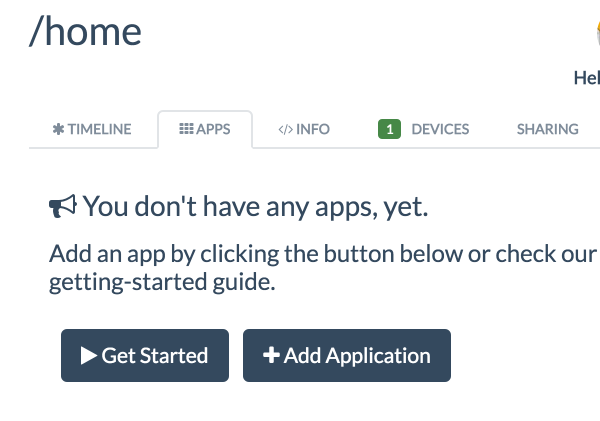
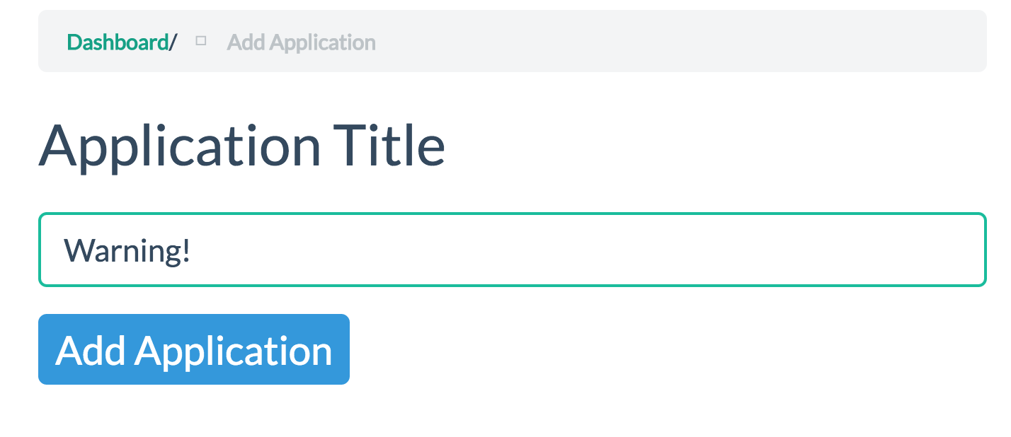
Click on "Add Application" to create a new application.
Name you application...
Now, it's time to add events to your application! Click on the "add Events". Instapush is events driven and we need to create an event to be triggered for us to actually get push requests.
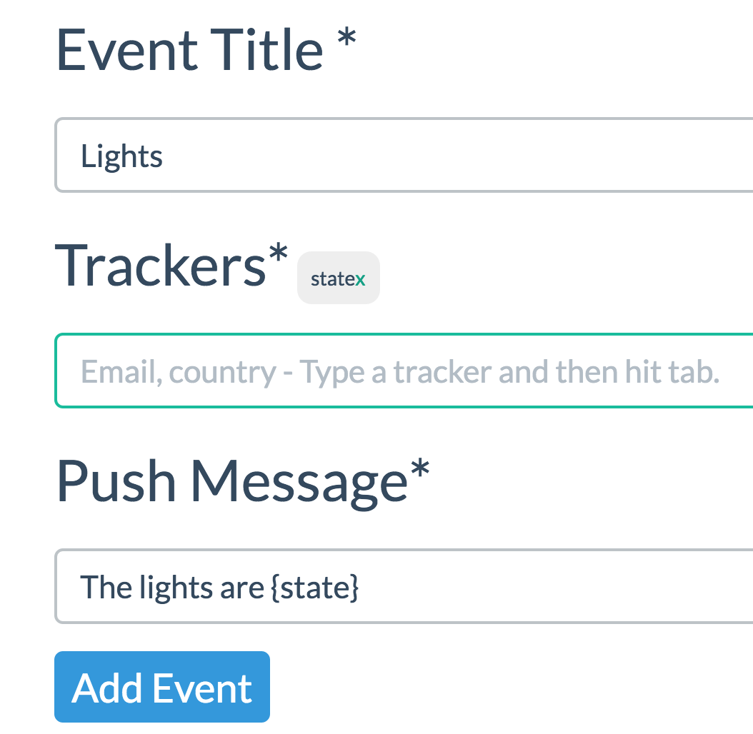
Each event has an Event Title, Trackers (parameters) and an actual notification message. The title is a well... title. For our project we will be tracking when the lights in a room are being turned on and off. So I gave the event title Lights. The trackers are the values you would want to pass to the message. In this case, I am going to have 2 of them. The first is "room" and the second will be "state". This allows for the app to scale beyond a very specific use case. You could see this expanding to every room in a house, though that's a lot of push notifications.
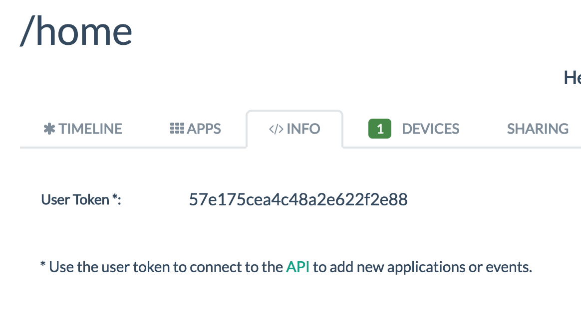
With that, you have created everything you need on their site. The only thing left is to collect some information. Your account is tied to a User Token, an Application ID and an Application Secret. You can find your User Token from the Info tab on yor dashboard
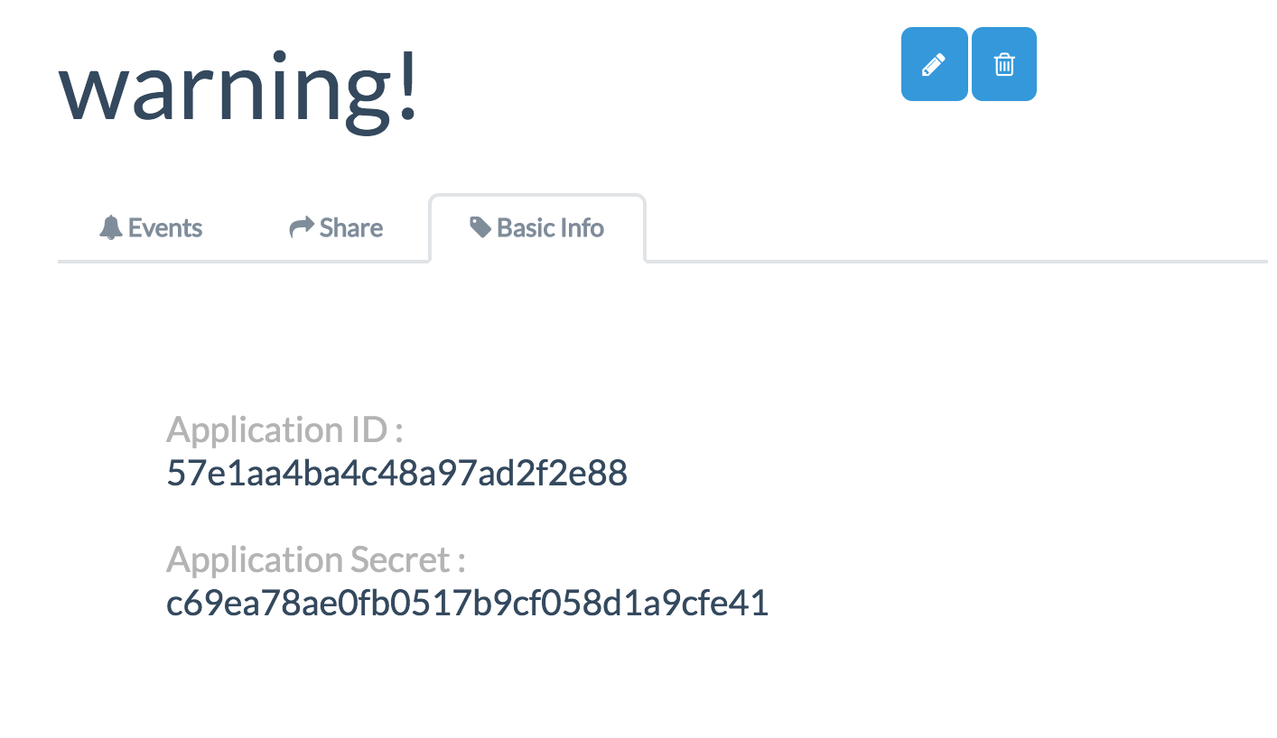
The App ID and Secret can be found on your applications dashboard under the Basic Info tab.
Now you are ready to write some code!
To use Instapush with Node.js we need to install the instapush module by typing the following command.
That's it! Now let's create a new project javascript file by typing the following into our console.
touch sensor_push.js
Now go ahead and open your new file with your text editor and type out or copy and paste the following code into it. Be sure to add your Token, App ID and App secret to your instapush.settings()
language:javasctipt
const instapush = require('instapush');
const five = require('johnny-five');

const board = new five.Board();

instapush.settings({
  token:'<your user token>',
  id:'<your app id>',
  secret:'<your app seceret>',
});

console.log('waiting for push notification');

board.on('ready', ()=>{

   const light = new five.Sensor({
      pin: 'A0',
      freq: 10* 1000
   });

   light.on('change', ()=>{
      if(light.val >= 900){
         instapush.notify({"event":"Warning!","trackers":{"room":"bedroom"},{"state":"on"}} ,(err, response)=>{
console.log(response);
         });
      }
      else if(light.val <= 400){
        instapush.notify({"event":"Warning!","trackers":{"room":"bedroom"},{"state":"off"}} ,(err, response)=>{
console.log(response);
        });
      }
   });
});
OK, now make sure you save this file and then run it by typing the following command in the console.
node sensor_push.js
Nothing should physically happen with your project. Go ahead turn your lights off. Your console should get this output.
{
"msg": "Notification Sent Succesfully",
"error": false,
"status": 201
}
Nice! Now check your phone. You should get a push notification that looks something like this.
With that you now have a way to track things happening real time with your phone. This could be your garage door opening, your oven being on, even the temperature somewhere. Pretty cool!
Now go! Create all of the push notifications you want! If you want to learn more about how to use the Instapush module you can learn more on its NPM page.
Experiment 6: LED.RGB
Introduction
Note: If you ARE using the Chrome App you will skip any console commands and run the example code directly in the app
You know what’s even more fun than a blinking LED? Changing colors with one LED. In this circuit, you’ll learn how to use an RGB LED to create unique color combinations. Depending on how bright each diode is, nearly any color is possible!
Parts Needed
You will need the following parts:
- 1x Breadboard
- 1x SparkFun RedBoard
- 1x Common Cathode RGB LED
- 3x 330Ω Resistors
- 6x Jumper Wires
Didn't Get the Tinker Kit?
If you are conducting this experiment and didn't get the Tinker Kit, we suggest using these parts:
Resistor 330 Ohm 1/6 Watt PTH - 20 pack
COM-11507
Introducing the Red Green Blue (RGB) LED
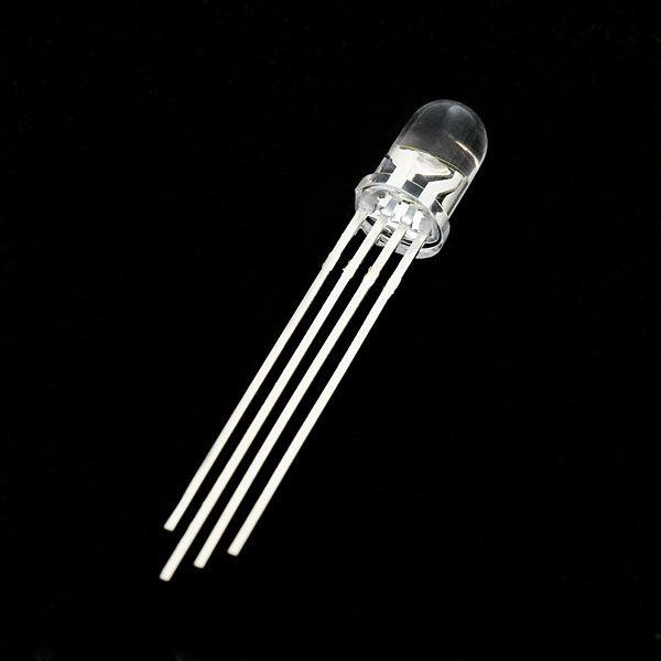
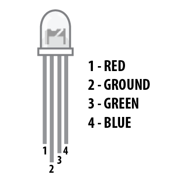
The Red Green Blue (RGB) LED is 3 LEDs in one. The RGB has four pins with each of the three shorter pins controlling an individual color: red, green or blue. The longer pin of the RGB is the common ground pin. You can create a custom colored LED by turning different colors on and off to combine them. For example, if you turn on the red pin and green pin, the RGB will light up as yellow.
But which pin is which color? Pick up the RGB so that the longest pin (common ground) is aligned to the left as shown in the graphic below. The pins are Red, Ground, Green and Blue -- starting from the far left.
Hardware Hookup
Ready to start hooking everything up? Check out the wiring diagram and hookup table below to see how everything is connected.
| Polarized Components | Pay special attention to the component’s markings indicating how to place it on the breadboard. Polarized components can only be connected to a circuit in one direction. Polarized components are highlighted with a yellow warning triangle in the table below. |
Wiring Diagram for the Experiment

Writing the Script
Remember to Setup Your Project Directory!
From your `SIK` directory make sure that create a new project directory for this experiment and create an empty project by typing in the following commands while in your `SIK` directory.
mkdir exp_06;cd exp_06;
npm init -y;
npm install johnny-five
Once done you will have created a project directory, moved into it, created an npm project and installed Johnny-Five. Wahoo!
Create a new file called "rgb.js" by typing the following command into your command line prompt.
touch rgb.js
Now open your rgb.js file with a text editor and either type out or copy and paste the following code into it.
language:javascript
const five = require('johnny-five');
const board = new five.Board();

board.on('ready', ()=>{
   const rgb = new five.Led.RGB({
      pins: {
         red: 5,
         green: 6,
         blue: 9
         },
      isAnode: false
   });

   rgb.color(255,0,0);
   board.wait(2000, ()=>{
      rgb.color('green');
      board.wait(2000, ()=>{
         rgb.color(##0000ff);
      });
   })
});
Code to Note
language:javascript
rgb.color(255,0,0);
You can specify the color of the RGB Led by using an RGB value, where each value is a range from 0 to 255. The first number is the red value, the second is green and the last is blue.
language:javascript
rgb.color('green');
You can also specify the color by name, similar to the basic color naming convention in HTML.
language:javascript
rgb.color(##0000ff);
Finally, you can specify the color by its hexidecimal value as well. This is great for matching the color of the LED to an specific color of your choice.
What You Should See
You should see your LED turn on, but this time in new, crazy colors! If it doesn't, make sure you have assembled the circuit correctly and verified and uploaded the code to your board, or see the Troubleshooting section.

Troubleshooting
Unexpected Colors
Check your wiring and pin numbers of the RGB. Remember that ground is the long leg of the LED!
RGB Not Working
Make sure you have the RGB in the correct orientation to the wiring diagram. It is just like any other LED and is polarized!
Seeing Red?
The red spectrum tends to run brighter than the other colors. Try adding a bit higher current limiting resistor to it, or if you don't have one, use a lower red value in your RGB values.
Still No Success
A broken circuit is no fun. Send us an email, and we will get back to you as soon as we can: techsupport@sparkfun.com
Manipulating Color beyond Color()
The RGB led also has all of the basic Led methods available to it such as the following.
rgb.on()
rgb.off()
rgb.blink()
rgb.fade()
You can also control the brightness of the led with the rgb.intensity() method which accepts a 0 to 255 value with 0 being off and 255 being full brightness.
Exploring Node.js
Node.js is javascript running on the "back end", or on servers. Well, what is it serving? Node.js makes serving web content super easy with a few lines of code. To make things even easier there is a module called Express that makes building web applications and handling http requests and responses even easier.
In this experiment you learned the basics of how to control an RGB. Lets now add a layer to that and control the RGBs color using an http request to set the color.
Express

Fast, unopinionated, minimalist web framework
As stated earlier we will be using Express. We will install Express through our trusty npm interface in the console. To install express navigate to your project directory and type the following command.
npm install express
Now, to create a new javascript file called "rgb_express.js" use the following command.
touch rgb_express.js
Use your text editor to open your new file and type out or copy and paste the following code into it.
language:javascript
const five = require('johnny-five');
const express = require('express');

const app = express();
const board = new five.Board();

board.on('ready', ()=>{
  const rgb = new five.Led.RGB({
    pins: {
      red: 9,
      green: 10,
      blue: 11
    },
    anode: false
  });

  app.get('/colors/:red-:green-:blue', (req,res)=>{

    var red = req.params.red;
    var green = req.params.green;
    var blue = req.params.blue;

    rgb.color(red,green,blue);

    res.end('Color requested: '+ req.params.red+','+req.params.green+','+req.params.blue);
    console.log('color received!');
  });
});

app.listen(8080, ()=>{
  console.log('listening on 8080');
});
Make sure you have saved your file and then run it from the console by typing the following command.
node rgb_express.js
The console will return with the following output...
language:console
listening on 8080
1475710622808 Device(s) /dev/cu.usbserial-DN01DHUL
1475710622815 Connected /dev/cu.usbserial-DN01DHUL
1475710626127 Repl Initialized
>> color received!
color received!
Now, open your browser and navigate to http://localhost:8080/colors/255-0-0. Your browser should return the following simple web page and your RGB should turn red.
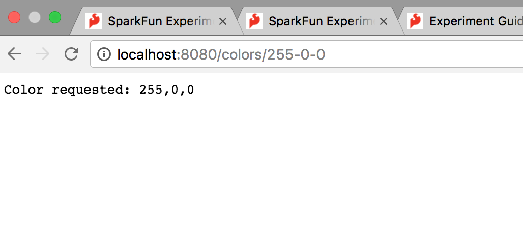
To change the color of your RGB in this way you change the ending part of the URL as an RGB value that is separated by a dash (-) rather than a comma. So, green would be 0-255-0. Each time you change the value and hit Enter, your browser will respond with the RGB value and the RGB color will change. Pretty cool, huh?!
Code to Note
To briefly cover Express like this is a bit of a shame, but we have circuits to build and code to write. If you are curious about Express and the ins and outs of it, check out their documentation here. But, we will take a look a quick look at how we accomplished this marvel.
language:javascript
const express = require('express');

const app = express();
Just like any other module express is added to your program using the require() statement. We can then create an instance of express (const app = express();).
language:javascript
app.get('/colors/:red-:green-:blue', (req,res)=>{
//do cool things when you get ...
});
Express does a lot of the leg work for us. In essence, by using Express we are creating an http server that will be listening to different requests and their types. Probably the most popular type of request is the GET request; which the basic type of request you can send by typing in a URL into your browser.
the app.get() method is essentially an event listener that reacts to a get request to the server. In this case when it gets the route or path of "/colors/:red-:green-:blue".
language:javascript
var red = req.params.red;
var green = req.params.green;
var blue = req.params.blue;
In our situation you may notice that the request URL has something odd. There are colons in front of the color names. That is to notate them as parameters that a user can pass and Express can use them as input data attached to the request or req object. We can access these values in the ways above. In short, the URL looks like the following: /colors/:red-:green-:blue. We can pass our app data by replacing the :red, :green and :blue parameters with 0-255 values like your original example for red. /colors/255-0-0.
language:javascript
res.end('Color requested: '+ req.params.red+','+req.params.green+','+req.params.blue);
    console.log('color received!');
Once we have captured the RGB values from the parameters and set the color of the RGB Express sends a response using the res.end() method. We simply send it the RGB value as a string and that gets printed in the browser. Not flashy by any means, but efficient.
language:javascript
   app.listen(8080, ()=>{
  console.log('listening on 8080');
});
Lastly, but not last (remember its asychrnous) by all means, we tell Express to listen on port 8080 and then log that information to the console.
To learn more about Express and how you can use in a much more indepth way you can start with its NPM page.
Experiment 7: Thermometer
Introduction
Note: If you ARE using the Chrome App you will skip any console commands and run the example code directly in the app
A temperature sensor is exactly what it sounds like – a sensor used to measure ambient temperature. In this experiment you will learn about controllers in Johnny-Five. Controllers are a way that Johnny-Five makes using specific sensors easier. A number of sensors and actuators that have a controller attached to them fall underneath their own component object class, in this case the Thermometer class.
Parts Needed
You will need the following parts:
- 1x Breadboard
- 1x SparkFun RedBoard
- 3x Jumper Wires
- 1x TMP36 Temperature Sensor
Didn't Get the Tinker Kit?
If you are conducting this experiment and didn't get the Tinker Kit, we suggest using these parts:
Temperature Sensor - TMP36
SEN-10988
Introducing the TMP36 Temperature Sensor
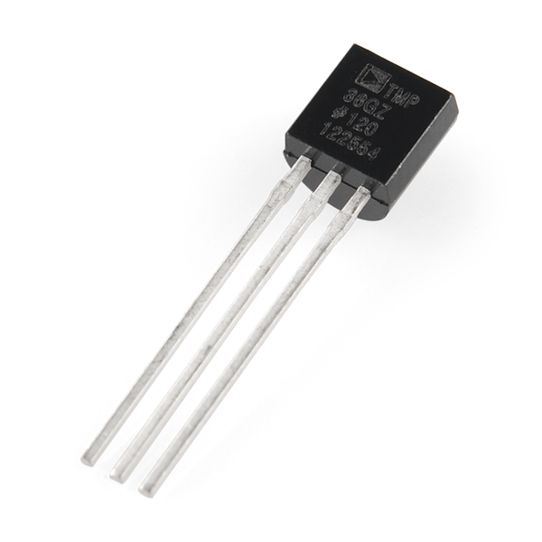
The TMP36 is a low-voltage, precision centigrade temperature sensor. It provides a voltage output that is linearly proportional to the Celsius temperature. It also doesn’t require any external calibration to provide typical accuracies of ±1°C at +25°C and ±2°C over the −40°C to +125°C temperature range. The output voltage can easily convert to temperature using the scale factor of 10 mV/°C.
If you are looking at the flat face with text on it, the center pin is your signal pin; the left-hand pin is supply voltage (5V in this tutorial), and the right-hand pin connects to ground.
In Johnny-Five the TMP36 falls under the Thermometer Object class. Other than the obvious, that it is a thermometer, the reason that the class exists and we dont just use the Sensor class is that a thermometer has a unit of measure, degrees and Fahrenheit, Celcius or if you are an uber nerd, Kelivn. The Thermometer class does all of the math for us to calculate the temperature from the raw sensor value we would normally get from the basic Sensorclass. This makes hooking up certain sensors and using them easier and faster to useful data. Let's check this out in action!
Hardware Hookup
Ready to start hooking everything up? Check out the wiring diagram below to see how everything is connected.
| Polarized Components | Pay special attention to the component’s markings indicating how to place it on the breadboard. Polarized components can only be connected to a circuit in one direction. |
Please note: The temperature sensor can only be connected to a circuit in one direction. See below for the pin outs of the temperature sensor -- TMP36.
Wiring Diagram for the Experiment

Writing the Script
Remember to Setup Your Project Directory!
From your `SIK` directory make sure that create a new project directory for this experiment and create an empty project by typing in the following commands while in your `SIK` directory.
mkdir exp_07;cd exp_07;
npm init -y;
npm install johnny-five
Once done you will have created a project directory, moved into it, created an npm project and installed Johnny-Five. Wahoo!
description...
language:javascript
const five = require('johnny-five');

const board = new five.Board();

board.on('ready', ()=>{

   const temp = new five.Thermometer({
      pin: 'A0',
      controller: 'TMP36'
   });

   temp.on('change', ()=>{
      var tempF = temp.fahrenheit;
      console.log('Temperature: ', tempF);
   });
});
Code to Note
language:javascript
const temp = new five.Thermometer({
      pin: 'A0',
      controller: 'TMP36'
   });
The thermometer object class allows you to set a controller. This accepts the model name of supported temperature sensors as a string. The idea behind a controller is that the calibration and the math to get the data from raw values to an actual temperature is done for you.
language:javascript
var tempF = temp.fahrenheit;
To read the temperature you can read either the fahrenheit, celcius or the kelvin parameter of the thermometer object. We stored it in a variable within the event function before logging it.
temp.F or temp.C instead if typing them out! What You Should See
You should be able to read the temperature your temperature sensor is detecting on the serial monitor in the Arduino IDE. If it isn't working, make sure you have assembled the circuit correctly and verified and uploaded the code to your board, or see the Troubleshooting section.
language:console
Temperature: 76
Temperature: 78
Temperature: 80
Temperature: 82
Temperature: 79
....

Troubleshooting
TMP36 is really hot!
Unplug your circuit immediately and check your wiring! You have hooked the TMP36 up backwards!
Now I get odd readings...
If you leave your TMP36 plugged in backwards for too long or you give it too much voltage you may damage it and cause it to malfunction.
Still No Success
A broken circuit is no fun. Send us an email, and we will get back to you as soon as we can: techsupport@sparkfun.com
Exploring Node.js
OK, so you now have access to reading the temperature, what now? Well, you could log it to a file as you did in Experiment 5. But, then you dont have access to it anywhere else. What if you wanted to see your log from your phone? Enter data.sparkfun.com!
phant is a modular logging tool developed by SparkFun Electronics for collecting data from the Internet of Things. phant is the open source software that powers data.sparkfun.com.
To get started with phant check out this guide to creating and setting up a data channel.
Create a channel by clicking the create button from the data.sparkfun.com home page. Fill out the form as shown here with your title and descript being different, but the field being the same.
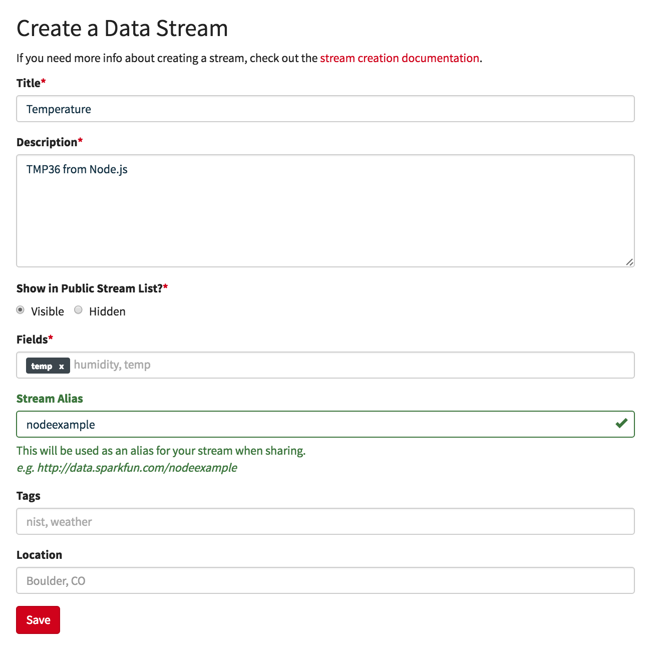
When you save the form data.sparkfun.com will assign you a set of keys. A public key, a private key and a delete key. It will also give you an example URL for submitting data via an http request.
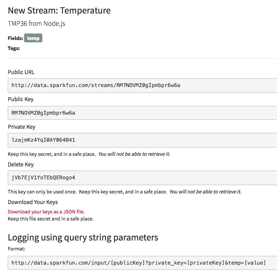
You will need your keys to interact with this, so be sure to email them to yourself!
With your channel now all setup, let's add some code to your original script for it to make an http request to your feed and report the temperature.
Request with data.sparkfun.com
Before we jump into code we need to install the request module. This module simplifies how to make http requests to other sites. You can install the module by running the following command in your console.
npm install request
With the module installed, let's now create a new file and call it "temp_phant.js" with the following command in your console.
touch temp_phant.js
Now open your temp_phant.js file in your text editor and type or copy and paste the following code into it.
language:javascript
const five = require('johnny-five');
const request = require('request');

const privKey = '<your private key>';
const pubKey = '<your public key>';

board.on('ready', ()=>{
   const temp = new five.Thermometer({
      pin: 'A0',
      controller: 'TMP36',
      freq: 10*1000
    });

   temp.on('data', ()=>{
      var tempF = temp.F;

      var logString = 'http://data.sparkfun.com/input/'+pubKey+'?'+'private_key='+privKey+'&temp='+String(tempF);

      request(logString, (error,res, body)=>{
         console.log(body);
      });
   });
});
Make sure you save your file and then run it by using the following command.
node temp_phant.js
Now after the script starts you should get the following log in your console.
language:console
1 success
As long as your script is running the room temperature will be reported to data.sparkfun.com every 10 seconds. Open a new browser window and navigate to your feeds public feed by typeing the following URL.
https://data.sparkfun.com/streams/
You should see a new row in the table get added every 10 seconds as shown below. Pretty cool!
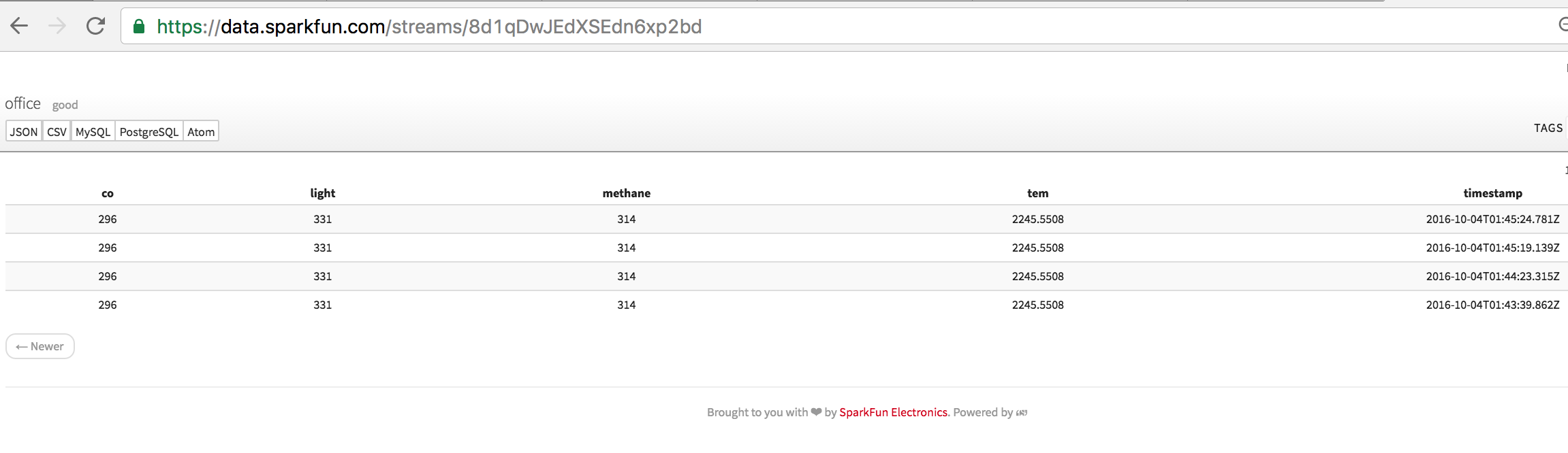
Now that you have this up and running, you can log data to the web for others to use! To learn more about Phant or install your own local Phant click the button bellow.
Experiment 8: Servo
Introduction
Note: If you ARE using the Chrome App you will skip any console commands and run the example code directly in the app
This experiment is your introduction to the servo motor, which is a smart motor that you can tell to rotate to a specific angular location. You will program it to rotate to a series of locations, then sweep across its full range of motion, and then repeat.
Parts Needed
You will need the following parts:
- 1x Breadboard
- 1x SparkFun RedBoard
- 1x Servo
- 3x Jumper Wires
Didn't Get the Tinker Kit?
If you are conducting this experiment and didn't get the Tinker Kit, we suggest using these parts:

Suggested Reading
Before continuing with this experiment, we recommend you be familiar with the concepts in the following tutorial:
Introducing the Servo Motor

Unlike the action of most motors that continuously rotate, a servo motor can rotate to and hold a specific angle until it is told to rotate to a different angle. You can control the angle of the servo by sending it a PWM (Pulse Width Modulation) pulse train; the PWM signal is mapped to a specific angle from 0 to 180 degrees.
Inside of the servo there is a gearbox connected to a motor that drives the shaft. There is also a potentiometer that gives feedback on the rotational position of the servo, which is then compared to the incoming PWM signal. The servo adjusts accordingly to match the two signals.
In this experiment, the servo is powered through 5 volts on the red wire, ground on the black wire, and the white wire is connected to a digital GPIO (General Purpose Input/Output) pin on which you can use PWM (11, 10, 9, 6, 5 and 3 on the RedBoard).
Hardware Hookup
Ready to start hooking everything up? Check out the wiring diagram below to see how everything is connected.
| Polarized Components | Pay special attention to the component’s markings indicating how to place it on the breadboard. Polarized components can only be connected to a circuit in one direction. |
Connect 3x jumper wires to the female 3-pin header on the servo. This will make it easier to breadboard the servo.
Wiring Diagram for the Experiment

Writing the Script
Remember to Setup Your Project Directory!
From your `SIK` directory make sure that create a new project directory for this experiment and create an empty project by typing in the following commands while in your `SIK` directory.
mkdir exp_08;cd exp_08;
npm init -y;
npm install johnny-five
Once done you will have created a project directory, moved into it, created an npm project and installed Johnny-Five. Wahoo!
Now, create a new javascript file called "servo.js" using the following command.
touch servo.js
Now open your servo.js file and either type out or copy and paste the following code in your file.
language:javascript
const five = require('johnny-five');

const board = new five.Board();

board.on('ready', ()=>{
   const servo = new five.Servo({
      pin: 9,
      range: [0,180]
      startAt: 90,
   });

   servo.sweep();
});
Once you are done, make sure to save your file and then run your script with the following command.
node servo.js
Once your script loads, your servo should start moving!
Code to Note
language:javascript
const servo = new five.Servo({
      pin: 9,
      range: [0,180]
      startAt: 90,
   });
Like any other component class objects, the servo has its own setup where you define a "shape". The servo has a number of shape parameters, many of them are optional, but make the functionality of using a servo easier in the long run. We tend to use the three above. You specify the pin number as well as the range as an array of two values. The first value of the array is the minimum angle and the second value is the maximum of the range. Finally we give a startAt value which is the angle at which you want the servo to start at. In this case 90 degrees.
language:javascript
servo.sweep();
Once the servo object is created we can now use any of the methods available to us. This script just uses the sweep() method which sweeps the servo hub back and forth between the minimum and maximum of the range parameter.
What You Should See
You should see your servo motor move to various locations at several speeds. If the motor doesn't move, check your connections and make sure you have verified and uploaded the code, or see the Troubleshooting section.

Troubleshooting
Servo Isn't Moving and is Hot
You are trying to write beyond the servos limits of 180 degrees or less than 0 degrees. Unhook the circuit to let the motor cool and check your code.
Servo still isn't Moving
Double check your wiring, you may have it hooked up to the wrong pin. Or, you may be trying to use a non-PWM pin. Make sure you are using PWM (~) pins with a servo.
Still No Success
A broken circuit is no fun. Send us an email, and we will get back to you as soon as we can: techsupport@sparkfun.comBeyond Sweep
min
The Servo.min() method takes the servo to its specified minimum which if is not defined is defaulted to 0.
max
The Servo.max() method takes the servo to its specified maximum position.
home
Servo.home() returns the servo to its specified home position. If this isn't specified the default is 90.
stop
Servo.stop() is used to, well, stop the servo from moving.
Exploring Node.js
Servos are used for a number of physical applications, a little known one is as an analog gauge needle. What better way to create an analog gauge other than to create a barometer / weather gauge for the weather in your area?
This project will read the weather from the Openweathermap service API and then move the servo accordingly to whatever weather conditions you put on a dial face.
Weather Gauge with openweathermap
Openweathermap is a free and open data source of weather all around the globe. It responds to API calls in a couple of different data formats, but we will be using JSON for our project which will simplify the parsing of the data. We will then write a servo angle depending on the weather condition.
A small abstraction layer for the openweathermap API
First of all, we need to install the openweathermap node module as well as the request module. Use the following command in your console to do so.
npm install openweathermap request
Signing up and Developer Keys
Signing up for Openweathermap is relatively painless! The reason that we need to create an account is so that we can gain access to an API key which we can create through our account. To sign up click Sign Up from their home page.

You sign up using your email address and create a password
Once you sign in you will be greeted by your user dashboard. You should see an API Keys tab. Click on it. This is where you can generate an API key and give it a name.
This is nice, because you can always come back to your account and access your API keys. No having the write them down or save them anywhere.
Working with the Openweathermap API
Now that you have the openweathermap module and an API key you can now use openweathermap in your Node.js project. You are going to build an analog gage that will tell you what to wear on a given day using a servo and data that you will request from openweathermap when you press a button.
Basic Open Weather Map Script
In your project directory create a file called "basicWeather.js" using the following command.
touch basicWeather.js
Now, open your basicWeather.js file and either type or copy and paste the following code into it. Be sure to insert your API key under the APPID parameter. You can also change the q parameter to your local city and state as well.
language:javascript
var weather = require('openweathermap');

var settings = {
   APPID:'<YOUR API from openweathermap>!',
   units: 'imperial',
   lang: 'en',
   q:'Boulder,CO'
   }

 weather.now(settings,(err,data)=>{
    console.log(data.main);
 });
Make sure you save your file and then run it using the following command.
node basicWeather.js
Once the script loads and executes you should get something similar to this output in your console.
language:console
{ coord: { lon: -105.27, lat: 40.01 },
 weather:
  [ { id: 801,
   main: 'Clouds',
   description: 'few clouds',
   icon: '02d',
   iconUrl: 'http://openweathermap.org/img/w/02d.png' } ],
 base: 'stations',
 main:
 { temp: 61.74,
   pressure: 1009,
   humidity: 25,
   temp_min: 60.01,
   temp_max: 64 },
 wind: { speed: 6.89, deg: 88, gust: 6.17 },
 clouds: { all: 24 },
 dt: 1475614410,
 sys:
  { type: 3,
    id: 63373,
    message: 0.1875,
    country: 'US',
    sunrise: 1475586107,
    sunset: 1475627773 },
 id: 5574991,
 name: 'Boulder',
 cod: 200,
 list: [] }
OK, so we just got a lot of data! But this gives us access to all of the weather data for our location. This data is in what is called JavaScript Object Notation, or JSON. If you take a closer look you will notice that the data is formatted similar to our javascript objects that have parameters with keys and values as well as arrays. Now, how do you parse, or break this data down into useful bits? Well let's just eyeball some useful bits from this.
First of all, the weather object would probably be useful. It gives us a general weather condition in terms of a description.
Next, the main object gives us the details in terms of temperature, humidity, etc.
Finally, the wind object gives us the wind speed, direction and gust conditions.
OK, all great...but now let's break it down!
You can use a dot notation for objects that are part of other objects in javascript if they are formatted this way. For example this whole readout is the data object. If we wanted to just look at the wind portion of the data object we could log data.wind to the console. Here is a modified version of our previous example that breaks the data down into useful chunks and stores them in variables and then logs them to the console. go ahead and create a new javascript file called "weatherParse.js" with the following command.
touch weatherParse.js
Now open your weatherParse.js file in a text editor and either type out or copy and paste the following script into it. Make sure that you use your API key.
language:javascript
var weather = require('openweathermap');

 var settings = {
     APPID:'<your api key>',
     units:'imperial',
     lang:'en',
     q:'Boudler,CO'
 }

weather.now(settings,(err,data)=>{
   var temp = data.main.temp;
   console.log('Current Temperature:', temp);
   var tempMax = data.main.temp_max;
   console.log('Todays High:', tempMax);
   var tempMin = data.main.temp_min;
   console.log('Todays Low', tempMin);
   var weather = data.weather[0].main;
   console.log('Todays Condition:', weather);
   var wind = data.wind.speed;
  console.log('Current Wind Speed:', wind);
});
Make sure you save your file and then run it with the following command.
node weatherParse.js
You should get similar data to this print out in your console.
language:console
Temperature: 61.48
Todays High: 64
Todays Low 59
Todays Condition: Clouds
Current Wind Speed: 4.61
OK, awesome! Now, let's create our gage! I created a cutting template for you to print out and then back with cardboard. I split the half circle into four different segments with each one being a different required article of clothing.
Once you have printed it out and backed it with some cardboard you can add a small dab of hot glue to the servo and glue it to the back as shown in the image below.
Now, create a small pointer out of cardboard and glue it onto one of the servo horns as shown.
We now need to calibrate the servo to be able to place the pointer correctly. Create a new javascript file called "90.js" with the following command.
touch 90.js
Open your 90.js file in your text editor and copy and paste the following code into it.
language:javascript
const five = require('johnny-five');

const board = new five.Board();

board.on('ready', ()=>{
   const servo = new five.Servo({
      pin: 9,
      range: [0,180]
      startAt: 90,
   });

   servo.to(90);
});
Save your file and then run it with the following command.
node 90.js
The servo will move to 90 degrees and then stop. Perfect! Press fit the pointer onto the servo hub with it pointing straight up as shown below.
Now, comes the final script!
Forecast and a Servo
For the final script create a new javascript file called "final.js" with the following command.
touch final.js
Now open your final.js file in your text editor and either type out or copy and paste the following code into it.
language:javascript
const five = require('johnny-five');
var weather = require('openweathermap');

 var settings = {
     APPID:'<your api key>',
     units:'imperial',
     lang:'en',
     q:'Boudler,CO'
 }


const board = new five.Board();

board.on('ready', ()=>{
   const servo = new five.Servo({
      pin: 9,
      range: [0,180]
      startAt: 90,
   });
   setInterval(()=>{
   weather.now(settings,(err,data)=>{
      var temp = data.main.temp;
      var tempMax = data.main.temp_max;
      var tempMin = data.main.temp_min;
      var weather = data.weather[0].main;
      var wind = data.wind.speed;

      if(temp > 80){
         //sun block
         servo.to(155);
      }
      else if(temp <70 && temp > 65){
         //tee shirt w/ sweatshirt
         servo.to(115);
      }
      else if(temp <40){
          //coat
          servo.to(75);
      }
      else if(weather ==='rain'||weather ==='shower rain'|| weather === 'thunderstorm'){
         //umbrella
         servo.to(25);
      }
      else{
         //error!
         servo.to(90);
      }
   });
   },60000*15);
});
Once you are done, make sure you save your file. Now, run it with the following command.
node final.js
When you start the script your servo should first move to 90 degrees if it is not already there and then move to a weather condition on the gage. If you let it run long enough, this script checks the conditions for updates every 15 minutes!
Sweet! Now you will never forget your coat again.
For more information on the Openweathermap module and API you can check it out on its NPM page.
Experiment 9: Motor
Introduction
Note: If you ARE using the Chrome App you will skip any console commands and run the example code directly in the app
How could you make a motor spin in different directions? With an H-Bridge! In this experiment you will use the H-Bridge to control the motor's direction and speed.
Parts Needed
You will need the following parts:
- 1x Breadboard
- 1x SparkFun RedBoard
- 1x SN754410 H-Bridge IC
- 1x 48:1 Geared Motor
- 12x Jumper Wires
Didn't Get the Tinker Kit?
If you are conducting this experiment and didn't get the Tinker Kit, we suggest using these parts:
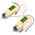

Introducing the H-Bridge
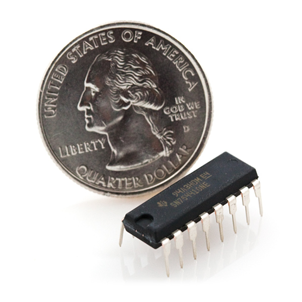
The SN754410 is an Integrated Circuit (IC), called an H-Bridge, that makes controlling motors easier. An H-Bridge allows you to control both the direction and the amount of an electrical current being supplied to a motor. You can think of it as a smart valve that allows you to change the direction of the current passing through the motor.
To switch the direction of the current, you use two pins to toggle pins on the board either HIGH or LOW. If the two direction pins are both HIGH or LOW at the same time, that causes the board to brake the motors. If one pin is HIGH and the other is LOW, the motor spins in one direction. If you flip-flop the states, the motor spins in the opposite direction. The IC is also powered separately with 5V supplied to pin 16 on the IC, and up to 36V for the motor voltage on pin 8 of the IC.
You can control up to two motors with a single IC. You can use this diagram as a reference for pin numbers in conjunction with the table below.
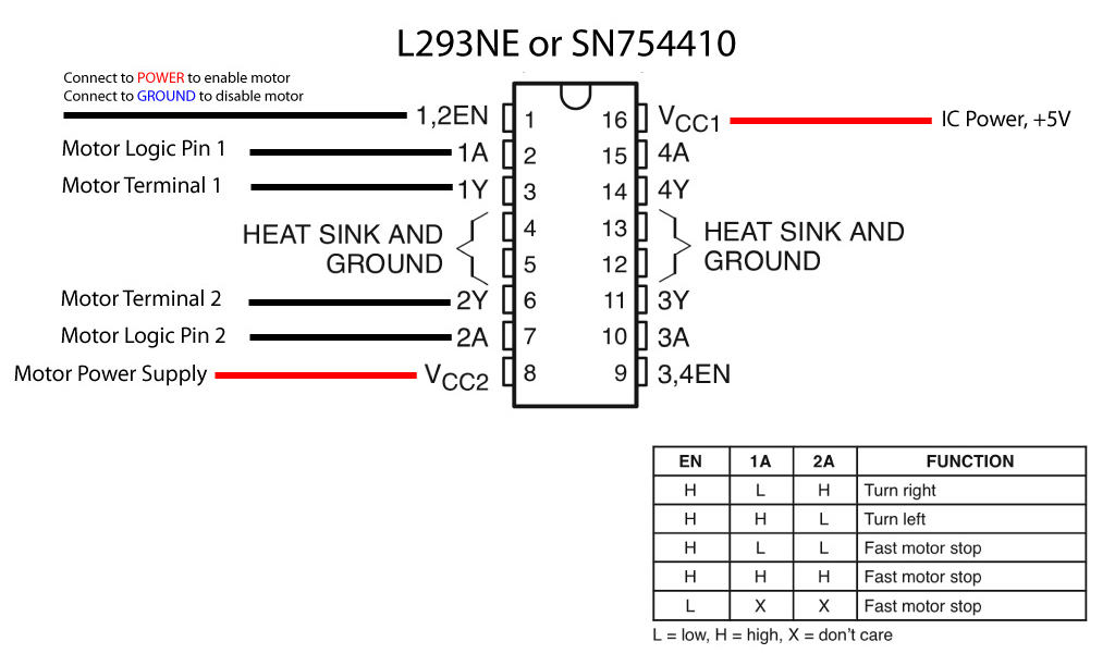
Hookup Table
| 1 | PWM signal for controlling the speed of motor A |
| 2 | Direction pin 1 for motor A |
| 3 | Motor A connection 1 |
| 4 | Ground / Heat Sink |
| 5 | Ground / Heat Sink |
| 6 | Motor A connection 2 |
| 7 | Direction pin 2 for motor A |
| 8 | Motor supply voltage |
| 9 | PWM signal for controlling the speed of motor B |
| 10 | Direction pin 1 for motor B |
| 11 | Motor B connection 1 |
| 12 | Ground / Heat Sink |
| 13 | Ground / Heat Sink |
| 14 | Motor B connection 2 |
| 15 | Direction pin 2 for motor B |
| 16 | Chip voltage (5V) |
Hardware Hookup
Ready to start hooking everything up? Check out the wiring diagram below to see how everything is connected.
| Polarized Components | Pay special attention to the component’s markings indicating how to place it on the breadboard. Polarized components can only be connected to a circuit in one direction. |
Wiring Diagram for the Experiment

Write your Script
Remember to Setup Your Project Directory!
From your `SIK` directory make sure that create a new project directory for this experiment and create an empty project by typing in the following commands while in your `SIK` directory.
mkdir exp_09;cd exp_09;
npm init -y;
npm install johnny-five
Once done you will have created a project directory, moved into it, created an npm project and installed Johnny-Five. Wahoo!
Create a new file called "motor.js" from the command line using the following command.
touch motor.js
Now, use a text editor to open your motor.js file and type out or copy and paste the following code into it.
language:javascript
const five = require('johnny-five');

const board = new five.Board();

board.on('ready', ()=>{
   const motor = new five.Motor({
      pins:{
         pwm: 6,
         dir: 5,
         cdir:4,
         },
      invert: false
   });

   motor.forward(255);

   motor.on('forward', ()=>{
      console.log('motor driving forward');
      board.wait(2000, ()=>{
         motor.brake();
      });
   });

   motor.on('brake', ()=>{
      console.log('motor braked');
      board.wait(2000, ()=>{
         motor.forward();
      });
});
Make sure you save your file and then run it from the console by typing the following command.
node motor.js
Code to Note
language:javascript
const motor = new five.Motor({
      pins:{
         pwm: 6,
         dir: 5,
         cdir:4,
         },
      invert: false
   });
When you create a motor component class object with this specific H-Bridge you have to specify three different pins: PWM, or the speed pin and then two directions pins. In this case 6,5 and 4 respectively. Notice that the pins parameter is an object by itself. There is also an option to invert your logic with an invert parameter. We set this to false.
language:javascript
 motor.forward(255);
Once you have created the motor object you can then use the direction methods that are connected to it. In this case we used the forward() method. We pass the method an 8 bit (0 - 255) speed value.
language:javascript
motor.on('forward', ()=>{
      console.log('motor driving forward');
      board.wait(2000, ()=>{
         motor.brake();
      });
   });
The direction methods have event emitters connected to them and so there is also event listeners. In this case the forward event listener is triggered when the forward() method is called. In this example we log a message and then after 2 seconds we call the motor.brake() method.
language:javascript
motor.on('brake', ()=>{
      console.log('motor braked');
      board.wait(2000,()=>{
      board.forward(255);
      });
   });
The brake event listener is similar to the forward event listener. This time we then call the forward() method again which will put this into an event based loop of driving forward and braking every 2 seconds.
What You Should See
When you start your script the motor will spin in one direction at full speed for two seconds (2000 milliseconds) and then stop. Your console will also log motor driving forward and motor braked respectively over and over again.
language:console
motor driving forward
motor braked
motor drive forward
motor braked
...
Troubleshooting
Motor Not Spinning
This is your first encounter with an IC! Make sure that the chip is seated into the breadboard snuggly and none of the pins aren't bent underneath the chip
Still nothing...
There are a lot of pins and wires in play! Double check your circuit and that the pins you specify in your code are the ones that you have wired up!
Motors directions are backwards!
Forward and reverse are arbitrary directions in code! If your motor is going in the opposite direction of your "forward", swap the motor wires where they connect to the breadboard.
Still No Success
A broken circuit is no fun. Send us an email, and we will get back to you as soon as we can: techsupport@sparkfun.com
Beyond forward and reverse
motor.fwd() is an alias for the forward() method
motor.rev() is an alias for the reverse() method
motor.stop() is a coasting stop, doen't hard stop the motor
motor.start() is used to restart the motor in its current direction.
motor.release() is similar to start() but used after the brake() method, releasing the brake!
Exploring Node.js
Motors are great! They are even better when you can automate what they do, especially from a user interface when you can just select an option and not have to do any more programming. Its a great way to be able to test things like motors and projects that have similar circuits. Sometimes it seems a little daunting to build those tools, but command line tools like Inquirer make it easier to build a menu based interface for your project!
Inquirer
A collection of common interactive command line user interfaces.

Inquirer is a module that allows you to build simple, command line based menus for your Node.js apps. In this case we will use it to build menu for different motor functions. The motor function options that we want are as follows:
- forward (full speed)
- reverse (full speed)
- on/off "blink" (forward)
- ramp up (acceleration)
- off
OK, let's get on this! Start by installing the inquirer module with the following command.
npm install inquirer
Testing Inquirer
Next, we will want to give Inquirer a test run. Create a new javascript file called "inqTest.js" using the following command.
touch inqTest.js
Now open your inqTest.js file in your text editor and copy and paste or type out the following code into the file.
language:javascript
var inquirer = require('inquirer');

inq();

function inq() {
  inquirer.prompt([
    {
     type: 'list',
     name: 'macro',
     message: 'What do you want your motor to do?',
     choices: [
       'Forward (full speed)',
       'Forward (half speed)',
       'Reverse (full speed)',
       'Reverse (half speed)',
       'On/Off ("Blink")',
       'Ramp Up',
       'Off'
       ]
    }
  ]).then(function (answers) {
      switch(answers.macro){
        case 'Forward (full speed)':
          console.log('Forward (full speed)');
          break;
        case 'Forward (half speed)':
           console.log('Forward (half speed)');
           break;

        case 'Reverse (full speed)':
           console.log('Reverse (full speed)');
           break;

        case 'Reverse (half speed)':
           console.log('Reverse (half speed)');
           break;

        case 'On/Off ("Blink")':
           console.log('On/Off ("Blink")');
           break;

        case 'Ramp Up':
           console.log('Ramp Up');
           break;

        case 'Off':
          console.log('Off');
          break;

        default:
          console.log('default');
          break;
      }
     inq();
   });
 }
Make sure you save this file and then execute it using the following command.
node inqTest.js
This should launch your app in the command line with a simple menu that looks like the following.
language:console
? What do you want your motor to do? (Use arrow keys)
❯ Forward (full speed)
  Forward (half speed)
  Reverse (full speed)
  Reverse (half speed)
  On/Off ("Blink")
  Ramp Up
  Off
Now, this shouldn't actually control your motors yet. When you move the cursor up and down with your arrow key and make a selection by pressing the Enter key. The console should log your selection and then relaunch the menu. Awesome! Let's take a second and take a look at how this works because there are some things that are new to us.
Code to Note
language:javascript
inq();

function inq() {
   //define inq()
}
First of all we call a function called inq(), but then define that function below. This is called hoisting, meaning that you can define the function anywhere in your script and then use it above it.
language:javascript
inquirer.prompt([
    {
     type: 'list',
     name: 'macro',
     message: 'What do you want your motor to do?',
     choices: [
       'Forward (full speed)',
       'Forward (half speed)',
       'Reverse (full speed)',
       'Reverse (half speed)',
       'On/Off ("Blink")',
       'Ramp Up',
       'Off'
       ]
    }
  ])
The first part of our inq() function is the inquirer.prompt(). We define a few parameters. This is the type of the prompt, in this case a list. We give it a name; macro. and then a prompt message. This message will be shown at the top of our menu. Finally we pass our choices as an array of strings. Fewww...Done!
language:javascript
then(function (answers) {
      //do something if Promise returns a success!
      }
   });
This is new to us! This .then() concept is called promise based programming. Where you have what is called a Promise where you have an executor function that is passed two other functions. Those functions are the resolve and reject functions. In a simple way if the executor function resolves the promise, it runs the resolve function, if it is rejected by the promise then it runs the reject. There is a whole lot to the concept of promises, you can find out more here. For now, we have a single resolve function which includes a long Switch Case of our menu objects.
language:javascript
switch(answers.macro){
        case 'Forward (full speed)':
          console.log('Forward (full speed)');
          break;
        case 'Forward (half speed)':
           console.log('Forward (half speed)');
           break;

        case 'Reverse (full speed)':
           console.log('Reverse (full speed)');
           break;

        case 'Reverse (half speed)':
           console.log('Reverse (half speed)');
           break;

        case 'On/Off ("Blink")':
           console.log('On/Off ("Blink")');
           break;

        case 'Ramp Up':
           console.log('Ramp Up');
           break;

        case 'Off':
          console.log('Off');
          break;

        default:
          console.log('default');
          break;
      }
The Switch case is similar to an if() statement, but it instead of a boolean logic statement you pass it a variable and a number of cases that variable can match. When the variable match a case, that specific group of code is ran. For example if answers.macro matches Off the Switch case runs the code under that case. Notice that each case: is closed with a break; command which returns the function outside of the Switch case.
Adding Motor Functionality
OK, we have the major body of code figured out, we just now have to add the motor functionality to this code using Johnny-Five. Create a new javascript file called "final.js" by running the following command.
touch final.js
Now open your final.js file in your text editor and type or copy and paste the following script.
language:javascript
var inquirer = require('inquirer');
var five = require('johnny-five');

var board = new five.Board();

board.on('ready', ()=>{
  var motor = new five.Motor({
    pins:{
      pwm: 9,
      dir: 10,
      cdir: 11
     }
  });

  inq(motor);
});

function inq(motor) {
  inquirer.prompt([
    {
      type: 'list',
      name: 'macro',
      message: 'What do you want your motor to do?',
      choices: [
        'Forward (full speed)',
        'Forward (half speed)',
        'Reverse (full speed)',
        'Reverse (half speed)',
        'On/Off ("Blink")',
        'Ramp Up',
        'Off'
      ]
    }
  ]).then(function (answers) {
      console.log(answers.macro);
      switch(answers.macro){
        case 'Forward (full speed)':
          motor.forward(255);
          break;

        case 'Forward (half speed)':
          motor.forward(128);
          break;

        case 'Reverse (full speed)':
          motor.reverse(255);
          break;

        case 'Reverse (half speed)':
          motor.reverse(128)
          break;

        case 'On/Off ("Blink")':
          board.loop(2000,()={
            board.wait(1000,()=>{
              motor.forward(255);
            board.wait(1000,()=>{
              motor.brake();
            });
          });
          break;

        case 'Ramp Up':
          for(int i = 0; i <=255; i++){
            motor.forward(i);
            board.wait(100);
          }
          break;

        case 'Off':
          motor.brake();
          break;

        default:
          motor.stop();
          break;
       }
      inq();
    });
});
Make sure that you save your file and then execute it by running the following command.
node final.js
Now, the same menu will launch in your console but when you make a selection it will actually control your motor. Try it out! Then when the menu relaunches you can make a new selection. You now have a pretty cool command line tool to control a motor!
**Experiment 10: Going Wireless
Introduction
Note: If you ARE using the Chrome App you will skip any console commands and run the example code directly in the app
Letting You Off the Leash!
Ok, up to this point you have been working with your Arduino tethered to your computer. Which is great and all for basic learning, but who wants to deal with a USB cable? You want to go wireless, you want to place your project 20 feet away, down the hall or across your yard! Enter Xbee!
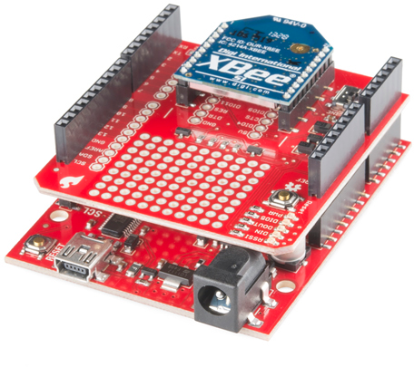
Xbee is a wireless module system created to take your project wireless and we have built a shield and breakout board kit so that you can use Xbee to take your Johnny-Five project to the next level.
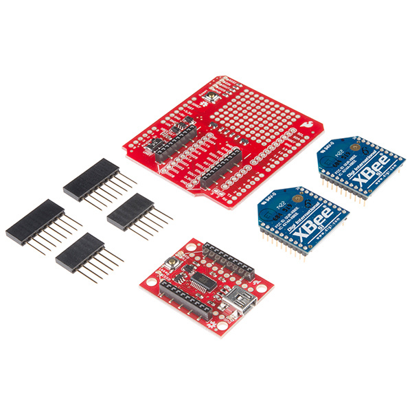
SparkFun XBee Wireless Kit
KIT-13197To get setup with Xbee we have created a hookup guide that will walk you through assembling the shield for your Arduino, setting the Xbee units up through using X-CTU which is the configuration software for Xbees and then getting your Arduino to talk to your computer through the shield, wireless modules and breakout board.
XBee Shield Hookup Guide
One you get your shield assembled and placed on your Arduino, go ahead and configure the Xbee modules as mentioned in the tutorial. Make sure that your Serial selection switch is on UART and not on DLINE as shown in the image below.
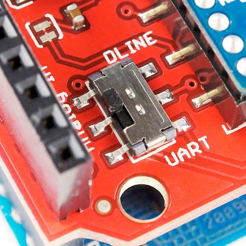
With the Arduino end setup, now plug in your second Xbee module that has been configured for the pair into the explorer board and use your USB cable to plug that into your computer.
With that you are ready to go and text your Johnny-Five script. For the sake of a quick test, you can just run a basic blink script on pin 13 with a an LED inserted into the headers as shown in the wiring diagram below with the Arduino powered from a seperate power source other than a USB port of your computer. These power sources could be a wall wart power supply plugged into the barrel jack, a battery pack or even a USB wall charger.
Now, either run your original blink script from Experiment 1 or create a new blink.js file by typing the following command.
touch blinkXbee.js
Then open the file and copy and paste the following code into it.
language:javascript
const five = require('johnny-five');
const board = new five.Board();

board.on('ready', ()=>{
   const led = new five.Led(13);

   led.blink();
});
Make sure that you save your script and then run your script with the following command.
node blinkXbee.js
Your script will execute the same way it would as if you had it plugged into a USB cable, but this time the Xbees are doing the communication work. Your project should now be portable and you can place it wherever you want within the Xbees range and then control it from your computer. Pretty snazzy!
Exploring Node.js
OK, so blink isn't that great of example. But, how about a robot? Let's build a quick cardboard robot to put your skills as an embedded Javascript developer to good use. We are going to building a NodeBot!
NodeBots?

NodeBots isnt really a Node module or a some fancy new developers tool. It's an idea! A group of people with a foot in Javascript and one in the world of robotics.
In fact, there is a whole day allocated to learning about and building NodeBots... International Nodebots Day
NodeBots Day is world wide event where people learn how to control the physical world with JavaScript. We want you to leave with the satisfaction of making something awesome! Each event has experts on hand to help you build your project and start you on the path to building awesome devices. Overall we're going to get together, collaborate and hack. The focus of NodeBots Day is on sharing and enjoying each other's company and JavaScript. Lots of JavaScript.
Let's Build a NodeBot using what we have learned!
Building a NodeBot
We are going to split this project into three sections. The chassis or the physical structure of your robot, the electronic circuits and finally the code to run your bot.
Before you dive in there are a few parts that are required to build a complete NodeBot. You may have some of these parts already depending on what hardware kit you are working from. Here is a list of the required commercial products from us.
The Chassis
We are going to build a super cheap and quick chassis out of some cardboard that you may have laying around, perhaps from the box that your kit came in. You will need a sheet that is about the size of a piece of printer paper (8.5" x 11").
Our basic robot will end up looking something like the robot below. It's not fancy, but it gets the job done.
We will start by cutting the shape out of the cardboard. For your reference we have included a cutting template if you are a person that is not skilled in measuring and accuracy, or you just want to get it done correctly. You can download the template here and print it out at full scale on a plain piece of printer paper and then cut it out.
You can then trace that template onto a piece of cardboard and then cut that our using a craft knife or scissors.
With the body cut from the cardboard you can now punch a hole through the center as shown with a pencil. This is where the motor wires and battery pack barrel jack will pass through so we can hook them up to the Arduino.
Now, find your two motors and glue them to the bottom of the chassis with a couple of dabs of hot glue as shown in the image below.
Once the glue cools you can do the same with the battery pack. Glue it to the bottom of your robot between the two motors, just behind the hole for the wires.
Now, add your wheels to your motor hubs
Pass the motor wires and the battery pack wires through the hole in the center of the chassis.
You can now mount your Arduino with the Xbee shield on it and a breadboard as shown below.
The final step in the chassis build is adding a skid for the robot to slide around on. With the way the robot is weighted in this configuration we found that putting a skid in the back of the robot works best. If you find that your robot is different than ours, feel free to make the neccesary modifications.
We built our skid from a piece of cardboard bent into a "V" and then hot glued to the bottom of our robot in the back. Again, we are going for simple not pretty.
With that, you have a finished chassis! Since this thing is made out of cardboard it is easy to modify and make better. Once you get it up and running feel free to add parts to it, decorate it or even take it apart and rebuild it with different materials.
The Circuit
The basic circuit for this Nodebot is an expansion of Experiment 9 where you wired a motor using an H-Bridge. This time you will be using 2 motors with an included potentiometer. The potentiometer will be the way that you will set the speed of your nodebot.
Using the breadboard on the robot, and the H-Bridge included in your kit, build the following circuit.
The Circuit Diagram
The Script
In terms of your script, let's write a simple test script to make sure your motors are up and running and spinning in the correct direction.
In your project directory create a new javascript filed called "drive.js" by typing the following command.
touch drive.js
Now open your drive.js file in your text editor and type out or copy and paste the following script.
language:javascript
const five = require('johnny-five');
const board = new five.Board();

board.on('ready', ()=>{
    const motors = new five.Motors([
     { dir: 4, cdir: 5, pwm: 6 },
     { dir: 7, cdir: 8, pwm: 9 },
     ]);

   const pot = new five.Sensor('A0');

   pot.on('change', ()=>{
      motors.forward(pot.analog);
   });
});
Once you are done, go ahead and save this file and then run it by typing the following command in your console.
node drive.js
Once your script executes go ahead and adjust your potentiometer. When you twist it, the motors speed should adjust accordingly. Both of your motors should be driving forwards! If yours aren't, revese the wiring of the motor(s) where it hooks to the H-Bridge. Both of your motors should now be driving forward at a speed set by your potentiometer as shown in the video.
Using Your NodeBot
Awesome! You now have your own working NodeBot that you can program wirelessly from your computer. But wait, we have one more addition to your NodeBot before we let you go off into the world with your new found knowledge in JavaScript and electronics.
Do you remember the keyPress module that you used in Experiment 3? Yep, you are probably thinking the same thing! Let's drive this NodeBot with the arrow keys of your computer!
Before we write any code lets install the keypress module into our project directory! Type the following command.
npm install keypress
Now, create a new javascript file called "keyDrive.js" by typing the following command.
touch keyDrive.js
Now, open your new keyDrive.js file and either type out or copy and paste the following script into it.
language:javascript
const five = require('johnny-five');
const keypress = require('keypress');

const board = new five.Board();

const press = keypress();

board.on('ready', ()=>{

   ....

});

console.log('Robot ready to go! Drive it with your arrow keys!');
Make sure that you save your file and the run it by typing the following command.
node keyDrive.js
Once your script executes and you see the console print out the following
Robot ready to go! Drive it with your arrow keys!
Press the UP arrow on your keyboard. Your robot should start moving foward. When you release it, it should stop. The RIGHT and LEFT keys should pivot the robot in those directions and the DOWN key should drive the bot in reverse. Pretty sweet!
Troubleshooting
Robot Spins in a Circle
One of your motors is wired backwards. Find the motor that is going in the opposite direction and flip its wiring to the H-Bridge.
Not Working!
Double check that you have correctly setup your Xbees and they are paired!
Still Nothing!
Make sure the serial connection switch on the Xbee shield is set to UART and not DLINE.
Still No Success
A broken circuit is no fun. Send us an email, and we will get back to you as soon as we can: techsupport@sparkfun.com
With that, you have a robot you can drive around from your computer! Go forth, explore the possibilities and be sure to share your projects with us over social media!
Resources and Going Further
There are tons of sensors and shields you can hookup to an Arduino that will help take your projects to the next level. Here's some further reading that may help you along in learning more about the world of electronics. For more info on Arduino, check out these tutorials:
- Arduino Resources and Curriculum
- Arduino Comparison Guide
- Arduino Shields
- Installing Arduino
- Installing an Arduino Library
- Arduino Data Types
For more hardware related tutorials, give these a read: