SparkFun USB UART Breakout (CY7C65213) Hookup Guide
Contributors:
 SFUptownMaker
SFUptownMaker 
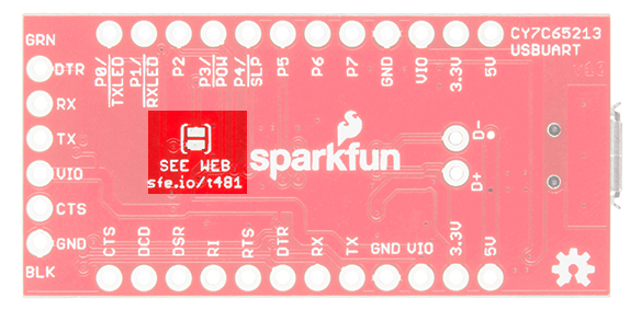
Hardware Overview
Here we will go over the various parts of the board, providing an explanation for each and detailed usage instructions.
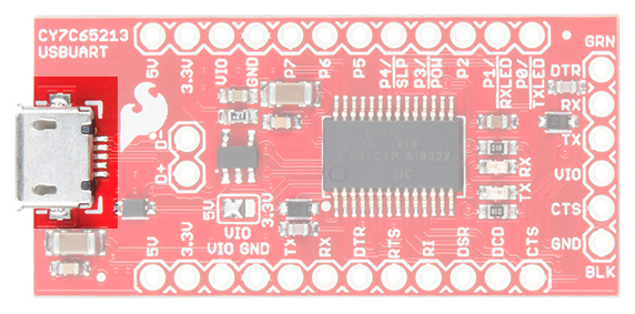
- Micro-B USB port---This is where the cable from the host device connects to this PC. Power can be supplied through this connector to this board, as well as to the circuit it is attached to.
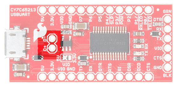
- USB signal lines---These two pads break out the D+ and D- signal lines for user access. These signals can then be brought out to a different connector if desired.
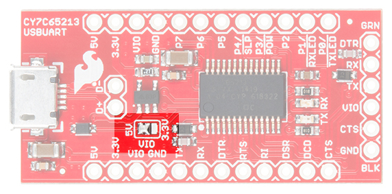
- VIO selection jumper---This jumper is used to select the voltage that appears at the VIO pin on the 6-pin serial header. The left two pads can be closed to supply 5V directly from the USB power line, or the right two pads can be closed to supply 3.3V via an onboard 500mA regulator. If the attached board is going to provide a voltage reference for an alternative voltage (say, 2.5V or 1.8V), remove all solder from this jumper.
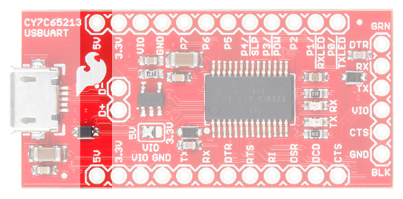
- ** 5V pin**---Supplies 5V directly from the USB power.
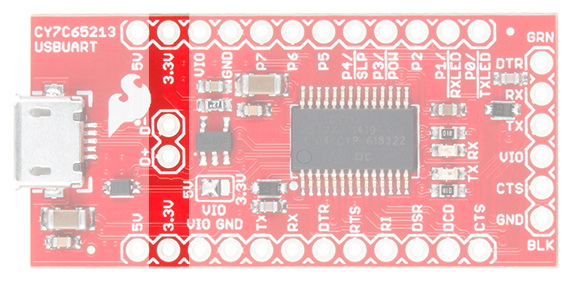
- 3.3V pin---Supplies 3.3V from a 500mA 3.3V regulator connected to the USB power line.
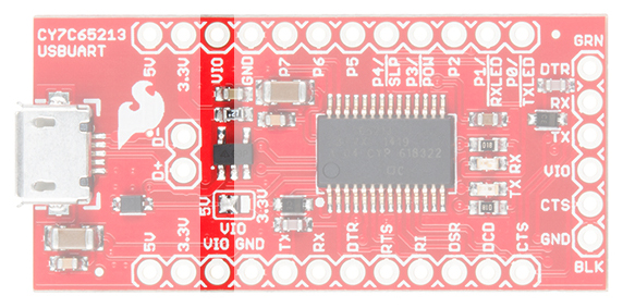
- VIO pin---Tied to the VIO pin on the 6-pin serial header, this will either be connected to 5V or 3.3V, depending on the VIO selection jumper, or it will reflect the voltage present on VIO if the downstream board is providing a reference voltage for this board.
- ** Variable purpose I/O pins**---The purpose of these pins will be discussed later, but in normal operation they are seldom, if ever, used.

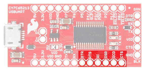
- DTE port pins---These pins provide the same functionality as the similarly named pins on an RS-232 port, albeit at VIO voltage rather than the bipolar voltage of true RS-232. DTR and CTS are the most commonly used. We'll discuss the role of these pins later.
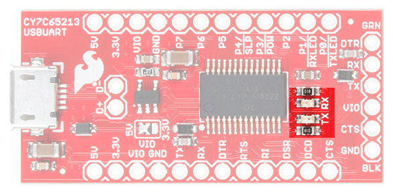
- TX and RX LEDs---These LEDs light up when data is being transferred over the serial channel. The TX LED lights up when data is being sent from the host to the attached board, and the RX LED lights up when data is being sent back from the attached board to the host.
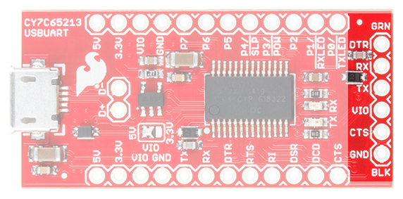
- 6-pin serial header---A longtime standard on SparkFun (and other) boards, this header contains the minimum necessary signals for communicating with a downstream board. It can be used to program Arduino Pro and Pro Mini boards, among others.
- Low-voltage select jumper---On the underside of the board, you'll find a jumper that should only be set in cases where VIO is 2V or less. Since there is no onboard reference for that voltage, this will be in cases where the downstream board is providing the reference voltage.