SparkFun SAMD21 Pro RF Hookup Guide
 Elias The Sparkiest
Programming the SAMD21 Pro RF
This modified example takes directly from the example code provided by the library with a two changes: the function calls to "Serial" will need to be replaced with "SerialUSB" and changes to the pin mapping that is consistent with the SAMD21 Pro RF. Before we look at the code you'll first need to modify the config.h file that came with the LMIC Arduino Library.
Configuring Your Region
Find your Arduino libraries folder and navigate to ...IBM_LMIC_framework/src/lmic/. You should find a file called config.h. Open it in any text editor and find the lines where CFG_us915 is defined. It should look like this:
language:c
//#define CFG_eu868 1
#define CFG_us915 1
// This is the SX1272/SX1273 radio, which is also used on the HopeRF
// RFM92 boards.
//#define CFG_sx1272_radio 1
// This is the SX1276/SX1277/SX1278/SX1279 radio, which is also used on
// the HopeRF RFM95 boards.
#define CFG_sx1276_radio 1
Since we're using the 915MHz radio module in the US, you need to make sure that the line #define CFG_us915 1 is not commented out and that the line #define CFG_eu868 1 is, by prepending // as shown above. Same goes for the radio type, we want #define CFG_sx1276_radio 1 and not #define CFG_sx1272_radio 1. Notice how the first "#define" contains "eu868", short for Europe and its center frequency. The line we un-commented contains "us915" which is undoubtedly for United States, with its center frequency at 915. With those changes made, save the config.h file and return to the Arduino IDE.
Configuring Your Device Key and Address
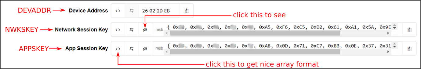
In order to make it work with your application, you'll need to copy in some keys from the Device Overview page on your TTN Console, so flip back to the browser tab with the Device Overview page loaded up.
You'll notice that, by default, the Network Session Key and App Session Key fields are obscured for security reasons. You can click the eye icon to show the code before copying it. Also, it will be easier to copy this into the example code if you click the <> button to show the codes in "C style", a bunch of HEX designated numbers.
You will need to copy three separate numbers into your example code from this page:
- Network Session Key =(i.e.
NWKSKEY[]) - App Session Key (i.e.
APPSKEY[]) - Device Address (i.e.
DEVADDR)
Here's a diagram explaining which field on this page corresponds to which constant in the example code:
Copy the modified code of the ttn-adb.ino sketch shown below and paste it in the Arduino IDE. Notice the three lines at the top of the code that say "NETWORK_SESSION_KEY_HERE", "APPLICATION_KEY_HERE", and "DEVICE_ADDRESS_HERE". These lines can be replaced by the keys from the website. Make sure to add a 0x before your device address.
language:c
#include <lmic.h>
#include <hal/hal.h>
#include <SPI.h>

// LoRaWAN NwkSKey, network session key
static const PROGMEM u1_t NWKSKEY[16] = { NETWORK_SESSION_KEY_HERE };

// LoRaWAN AppSKey, application session key
static const u1_t PROGMEM APPSKEY[16] = { APPLICATION_KEY_HERE };

// LoRaWAN end-device address (DevAddr)
static const u4_t DEVADDR =  DEVICE_ADDRESS_HERE ; // <-- Change this address for every node! For example, our device address is 26022DEN. We will need to replace "DEVICE_ADDRESS_HERE" as 0x26022DEB.

// These callbacks are only used in over-the-air activation, so they are
// left empty here (we cannot leave them out completely unless
// DISABLE_JOIN is set in config.h, otherwise the linker will complain).
// Well alright......
void os_getArtEui (u1_t* buf) { }
void os_getDevEui (u1_t* buf) { }
void os_getDevKey (u1_t* buf) { }

static uint8_t mydata[] = "Hello, world!";
static osjob_t sendjob;

// Schedule TX every this many seconds (might become longer due to duty
// cycle limitations).
const unsigned TX_INTERVAL = 5;

// Pin mapping
const lmic_pinmap lmic_pins = {
    .nss = 12,//RFM Chip Select
    .rxtx = LMIC_UNUSED_PIN,
    .rst = 7,//RFM Reset
    .dio = {6, 10, 11}, //RFM Interrupt, RFM LoRa pin, RFM LoRa pin
};

void onEvent (ev_t ev) {
    SerialUSB.print(os_getTime());
    SerialUSB.print(": ");
    switch(ev) {
        case EV_SCAN_TIMEOUT:
            SerialUSB.println(F("EV_SCAN_TIMEOUT"));
            break;
        case EV_BEACON_FOUND:
            SerialUSB.println(F("EV_BEACON_FOUND"));
            break;
        case EV_BEACON_MISSED:
            SerialUSB.println(F("EV_BEACON_MISSED"));
            break;
        case EV_BEACON_TRACKED:
            SerialUSB.println(F("EV_BEACON_TRACKED"));
            break;
        case EV_JOINING:
            SerialUSB.println(F("EV_JOINING"));
            break;
        case EV_JOINED:
            SerialUSB.println(F("EV_JOINED"));
            break;
        case EV_RFU1:
            SerialUSB.println(F("EV_RFU1"));
            break;
        case EV_JOIN_FAILED:
            SerialUSB.println(F("EV_JOIN_FAILED"));
            break;
        case EV_REJOIN_FAILED:
            SerialUSB.println(F("EV_REJOIN_FAILED"));
            break;
        case EV_TXCOMPLETE:
            SerialUSB.println(F("EV_TXCOMPLETE (includes waiting for RX windows)"));
            if (LMIC.txrxFlags & TXRX_ACK)
              SerialUSB.println(F("Received ack"));
            if (LMIC.dataLen) {
              SerialUSB.println(F("Received "));
              SerialUSB.println(LMIC.dataLen);
              SerialUSB.println(F(" bytes of payload"));
            }
            // Schedule next transmission
            os_setTimedCallback(&sendjob, os_getTime()+sec2osticks(TX_INTERVAL), do_send);
            break;
        case EV_LOST_TSYNC:
            SerialUSB.println(F("EV_LOST_TSYNC"));
            break;
        case EV_RESET:
            SerialUSB.println(F("EV_RESET"));
            break;
        case EV_RXCOMPLETE:
            // data received in ping slot
            SerialUSB.println(F("EV_RXCOMPLETE"));
            break;
        case EV_LINK_DEAD:
            SerialUSB.println(F("EV_LINK_DEAD"));
            break;
        case EV_LINK_ALIVE:
            SerialUSB.println(F("EV_LINK_ALIVE"));
            break;
         default:
            SerialUSB.println(F("Unknown event"));
            break;
    }
}

void do_send(osjob_t* j){
    // Check if there is not a current TX/RX job running
    if (LMIC.opmode & OP_TXRXPEND) {
        SerialUSB.println(F("OP_TXRXPEND, not sending"));
    }
    else{
        // Prepare upstream data transmission at the next possible time.
        LMIC_setTxData2(1, mydata, sizeof(mydata)-1, 0);
        SerialUSB.println(F("Packet queued"));
    // Next TX is scheduled after TX_COMPLETE event.
    }
}

void setup() {
    SerialUSB.begin(115200);
    // Serial communication on startup is not consistent on the SAMD21. The
    // following line waits for the serial monitor to be opened before
    // continuing. Uncomment if not needed.
    while(!SerialUSB);
    SerialUSB.println("Starting");

    // LMIC init
    os_init();
    // Reset the MAC state. Session and pending data transfers will be discarded.
    LMIC_reset();

    // Set static session parameters. Instead of dynamically establishing a session
    // by joining the network, precomputed session parameters are be provided.
    #ifdef PROGMEM
    // On AVR, these values are stored in flash and only copied to RAM
    // once. Copy them to a temporary buffer here, LMIC_setSession will
    // copy them into a buffer of its own again.
    uint8_t appskey[sizeof(APPSKEY)];
    uint8_t nwkskey[sizeof(NWKSKEY)];
    memcpy_P(appskey, APPSKEY, sizeof(APPSKEY));
    memcpy_P(nwkskey, NWKSKEY, sizeof(NWKSKEY));
    LMIC_setSession (0x1, DEVADDR, nwkskey, appskey);
    #else
    // If not running an AVR with PROGMEM, just use the arrays directly
    LMIC_setSession (0x1, DEVADDR, NWKSKEY, APPSKEY);
    #endif

    #if defined(CFG_us915)
    // NA-US channels 0-71 are configured automatically
    // but only one group of 8 should (a subband) should be active
    // TTN recommends the second sub band, 1 in a zero based count.
    // https://github.com/TheThingsNetwork/gateway-conf/blob/master/US-global_conf.json
    LMIC_selectSubBand(1);
    #endif

    // Disable link check validation
    LMIC_setLinkCheckMode(0);

    // TTN uses SF9 for its RX2 window.
    LMIC.dn2Dr = DR_SF9;

    // Set data rate and transmit power for uplink (note: txpow seems to be ignored by the library)
    LMIC_setDrTxpow(DR_SF7,14);

    // Start job
    do_send(&sendjob);
}

void loop() {
    os_runloop_once();
}
Configuring Serial for SAMD21
Below are a few modifications to the original code that will need to be made to tailor it to the SAMD21 Pro RF.
SerialUSBwhile(!SerialUSB)-- When the SAMD21 Pro RF starts up, it's not always a smooth transition and messages meant for the serial monitor will get missed. This line will hold your code hostage until you open the serial monitor at which point it will continue on. The SAMD21 Pro RF has two UART lines, SerialUSB references the one that communicates with the computer via the Micro-B connector.
Configuring SAMD21 Pro RF Pin Definitions
You'll need to change the pin mappings to be consistent with the reset, chip select, interrupt, and LoRaWAN lines of the RFM95W module.
language:c
const lmic_pinmap lmic_pins = {
    .nss = 12,//RFM Chip Select
    .rxtx = LMIC_UNUSED_PIN,
    .rst = 7,//RFM Reset
    .dio = {6, 10, 11}, //RFM Interrupt, RFM LoRa pin, RFM LoRa pin
};