SparkFun Qwiic Quad Solid State Relay Kit Hookup Guide
Hardware Overview
The Qwiic Quad Solid State Relay Kit builds on the design for our Qwiic Quad Relay using an ATTiny84 to act as the "brain" for the board. To allow for faster and quieter switching of the loads, this board uses solid state relays instead of electromechanical relays.
In this section we'll cover the hardware present on the Quad Solid State Relay Kit and note some of the unique functionality of the components.
Solid State vs Mechanical Relays
Let's talk briefly about two types of relays before we get into the details on everything included with the kit. A relay is a special kind of switch that has a switching mechanism inside isolated from the switch. This allows us to control the high-voltage output of the relay from a low-power input like a microcontroller.
Now let's compare an electromechanical relay (EMR) and a solid state relay (SSR). The primary difference is an EMR uses an electromagnetic field to physically close a switch inside the relay where a SSR uses a semiconductor like a MOSFET or an opto-isolator to switch the load on and off. This allows the SSR to switch at much higher speeds than an EMR and also increases their durability. Theoretically, and if used within spec, an SSR can last forever where EMR's are designed with an expected lifetime. EMR's are typically cheaper and also can allow multiple loads on a single relay (if it has multiple contacts) where SSR's are limited to a single load.
There is a lot of discussion out there about which type of relay is best but it really comes down to two things: budget and versatility. This brief outline covers the very basics of mechanical and solid state relays. Take some time to do a bit more research to help you decide which type of relay will be best suited for your project. For a short yet informative overview of electromechanical relays vs solid state relays, check out this blog post.
40A Solid State Relays
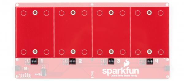
The kit includes four of our 40A Solid State Relays (SSR's) for you to assemble on to your board. Let's cover some characteristics from the relay's datasheet so you know what to expect from them and the Quad Solid State Relay.
| Characteristic | Range |
|---|---|
| Input Voltage | 3V-32V |
| Supply Current | 7.5mA @12V (40 mA @3.3V) |
| Load Voltage | 24-380VAC |
| Max Current (Through Relay) | 40A (@240 VAC) |
The relays use the Zero Cross trigger method so when operating on a 60Hz AC carrier signal you can switch the relays up to 120 times per second! Read on in the Arduino Examples and Python Examples sections where we'll demonstrate how to do that using a PWM signal.
The four 2-pin screw terminal blocks on the board connect the control signal inputs of the relays to the ATTiny84. The kit includes two lengths of wire for you to use to connect the relays to the board. Read on to the Hardware Hookup section for tips on assembling your kit.
One last note before we move on from the relays. The circuit for controlling the relays is designed for a Normally Open circuit only. This means your load is normally off until the relay is switched on. For more information on how this circuit is configured, check out the schematic and the relay datasheet.
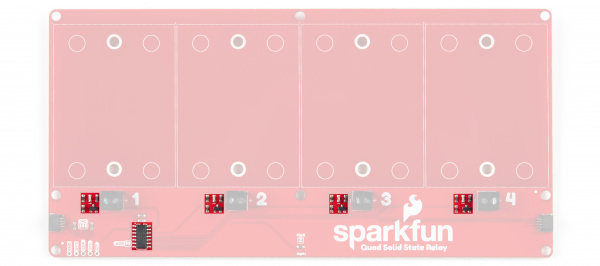
ATTiny84
The ATTiny84 on this board comes pre-programmed with firmware to control up to four relays via I2C commands. The ATTiny84's I2C address is 0x08 by default. Each relay control input is connected to an I/O pin on the ATTiny84 via a transistor circuit to protect the I/O pins as each relay takes ~40mA to toggle @3.3V. Each relay also has a blue STAT LED tied to the I/O circuit to indicate when the relay is on.
There is also a 2x3 header broken out on the back of the board for programming the ATTiny84. This is primarily used for programming during manufacturing but you can re-program the IC if you would like. You can download and modify the firmware from the Hardware GitHub Repository.
Power
Power for the board is provided either via the Qwiic interface or through the labeled 3.3V and GND pins broken out on the bottom left of the board.
Qwiic and I2C Interface
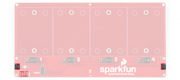
The I2C interface is broken out to two Qwiic connectors on either side of the board as well as 0.1"-spaced header pins for those who prefer a more traditional soldered connection.
Jumpers
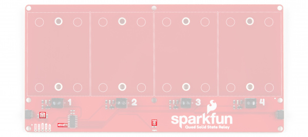
There are three jumpers on the Qwiic Quad Relay labeled PWR, I2C and ADR. The PWR jumper enables the Power LED, the I2C jumper pulls the SDA and SCL lines to 3.3V and the ADR jumper sets the I2C address of the ATTiny84.
Power Jumper
The power jumper (labeled PWR) controls voltage to the power LED on the board. This jumper is closed by default. To disable the power LED, simply open the jumper by severing the trace in between the two pads. Disabling the power LED can help reduce the total current draw of the board.
Address Jumper
The address jumper (labeled ADR) sets the I2C address for the ATTiny84. The jumper is closed by default with the address set to 0x08. Opening the jumper will change the address to 0x09.
I2C Jumper
The I2C Jumper pulls the SDA and SCL lines to 3.3V via two 4.7K Ohm resistors. The jumper is closed by default. Open this jumper if you have multiple devices connected to the bus with their own pull-up resistors enabled to avoid causing the parallel equivalent resistance creating too strong of a pull-up for the bus to operate correctly. As a general rule, disable all but one pair of pull-up resistors if multiple devices are connected to the bus.
Board Dimensions
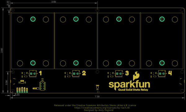
The Qwiic Quad Solid State Relay is quite large to fit all four relays and measures 7.30" x 3.30" (185.42mm x 91.44mm). There are eight mounting holes that fit a 4-40 screw.
With all the hardware included with the Qwiic Quad Solid State Relay covered, it's time to start assembling it!
