SparkFun Qwiic Digital Temperature Sensor - TMP102 Hookup Guide
 Alex the Giant, Ell C
 Introduction
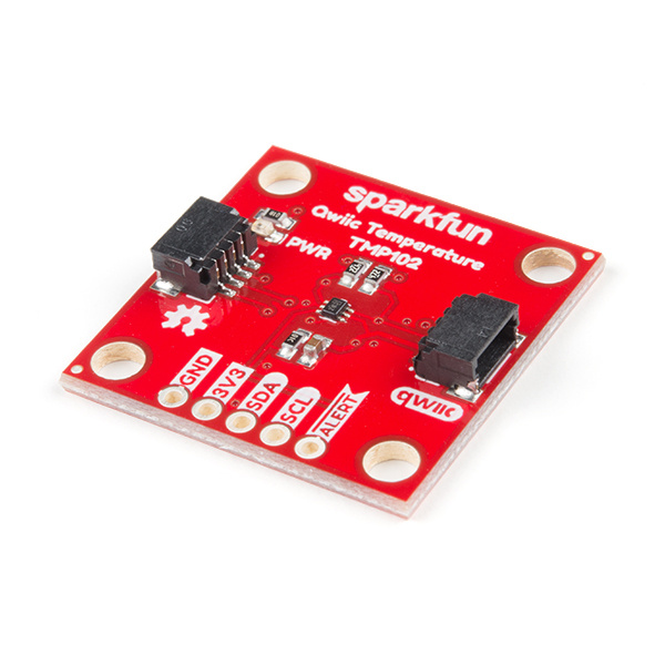
We all like to know the temperature, right? Well, with the SparkFun Digital Temperature Sensor - TMP102 (Qwiic) we've made this just about as easy as it gets. Based off of the original Digital Temperature Sensor Breakout - TMP102, we've added Qwiic connectors to bring this bad boy into our plug-and-play Qwiic Ecosystem, made the board just a bit bigger at 1" x1", and added an address jumper instead of breaking out the address pin. Let's dive in and have some fun!
Required Materials
To follow along with this tutorial, you will need the following materials. You may not need everything though depending on what you have. Add it to your cart, read through the guide, and adjust the cart as necessary.
Suggested Reading
If you aren't familiar with the Qwiic system, we recommend reading here for an overview.
| Qwiic Connect System |
We would also recommend taking a look at the following tutorials if you aren't familiar with them.
I2C
Analog vs. Digital
Serial Terminal Basics
Temperature Sensor Comparison
Hardware Overview
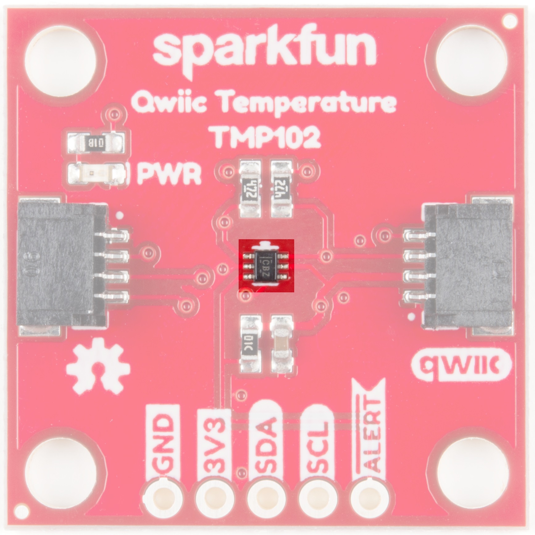
TMP102
Have you heard the phrase "Good things come in small packages"? Well, here's is a prime example! This board centers around Texas Instruments' TMP102 Low-Power Digital Temperature Sensor. This tiny little chip measures 1.6-mm × 1.6-mm and packs quite a nice punch. Here are some of the highlights, but feel free to check out the Datasheet for more information.
Highlights:
- Uses the I2C interface
- 12-bit, 0.0625°C resolution
- Typical temperature accuracy of ±0.5°C
- Supports up to four TMP102 sensors on the I2C bus at a time
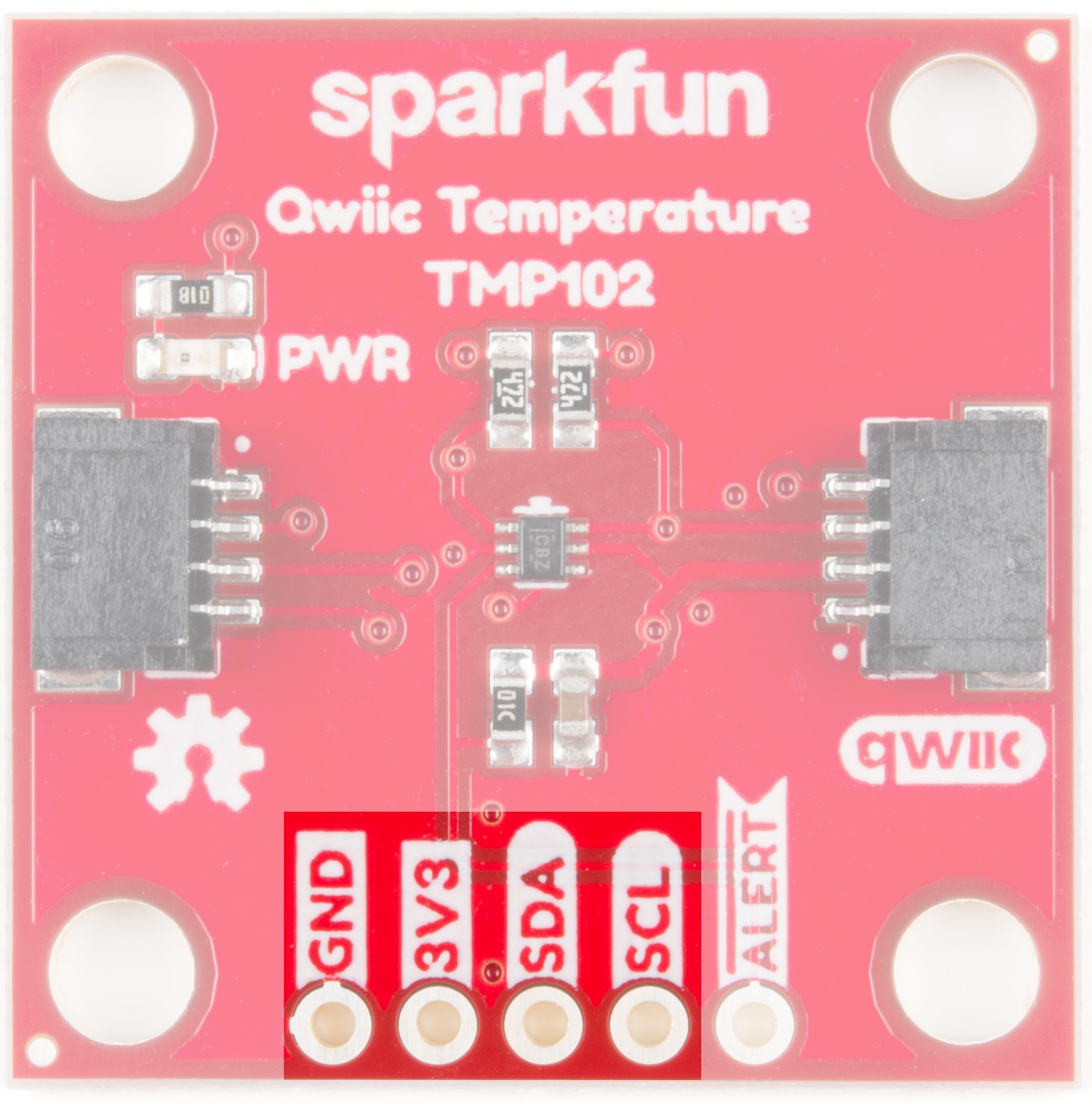
Power
Ideally, power will be supplied via the Qwiic connectors on either side of the board. Alternatively, power can be supplied through the header along the bottom side of the board labeled 3V3 and GND. The input voltage range should be between 1.4-3.6V.

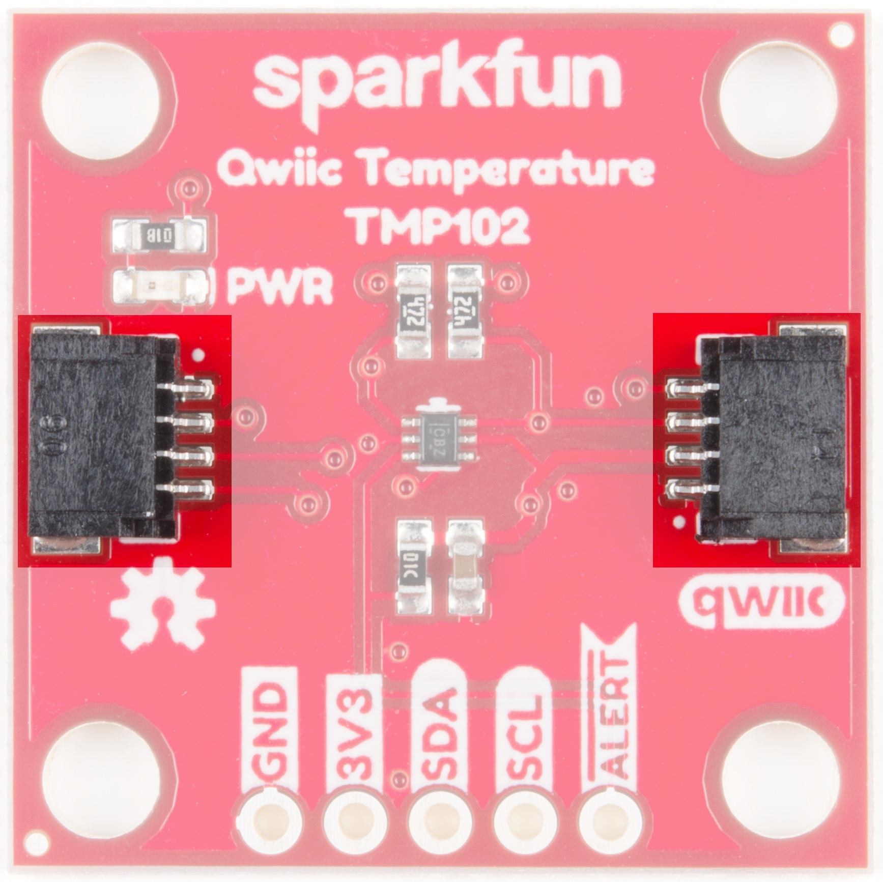
Qwiic Connectors
Our Qwiic Ecosystem makes sensors pretty much plug and play. There are two Qwiic connectors on either side of the Qwiic Temperature Sensor - TMP102 board to provide power and I2C connectivity simultaneously.
The I2C address of the board is 0x48 by default , but has 3 other addresses the board can be configured to use.
I2C Pins
The I2C pins break out the functionality of the Qwiic connectors. Depending on your application, you can connect to these pins via the plated through holes for SDA and SCL.
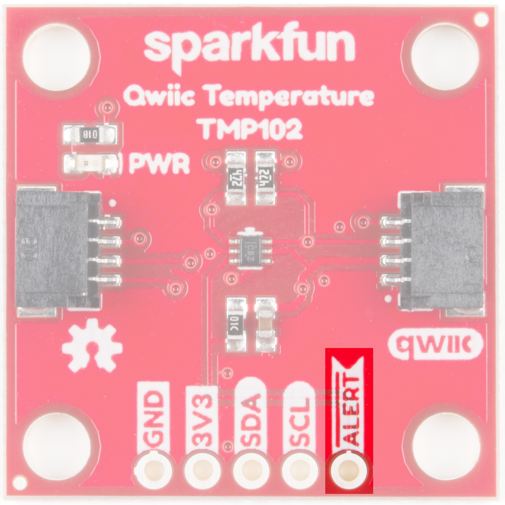
Alert Pin
The alert pin is an over temperature alert, which has an open-drain and is pulled up through a 10kΩ resistor. The alert can also be read over I2C as shown in the example in the Software Setup and Programming section.
Jumpers
I2C Jumpers
Like most (if not all) of our Qwiic boards, the TMP102 Temperature Sensor comes equipped with a pull-up resistor. If you are daisy-chaining multiple Qwiic devices, you will want to cut this jumper; if multiple sensors are connected to the bus with the pull-up resistors enabled, the parallel equivalent resistance will create too strong of a pull-up for the bus to operate correctly. As a general rule of thumb, disable all but one pair of pull-up resistors if multiple devices are connected to the bus. To disable the pull up resistors, use an X-acto knife to cut the joint between the two jumper pads highlighted below.
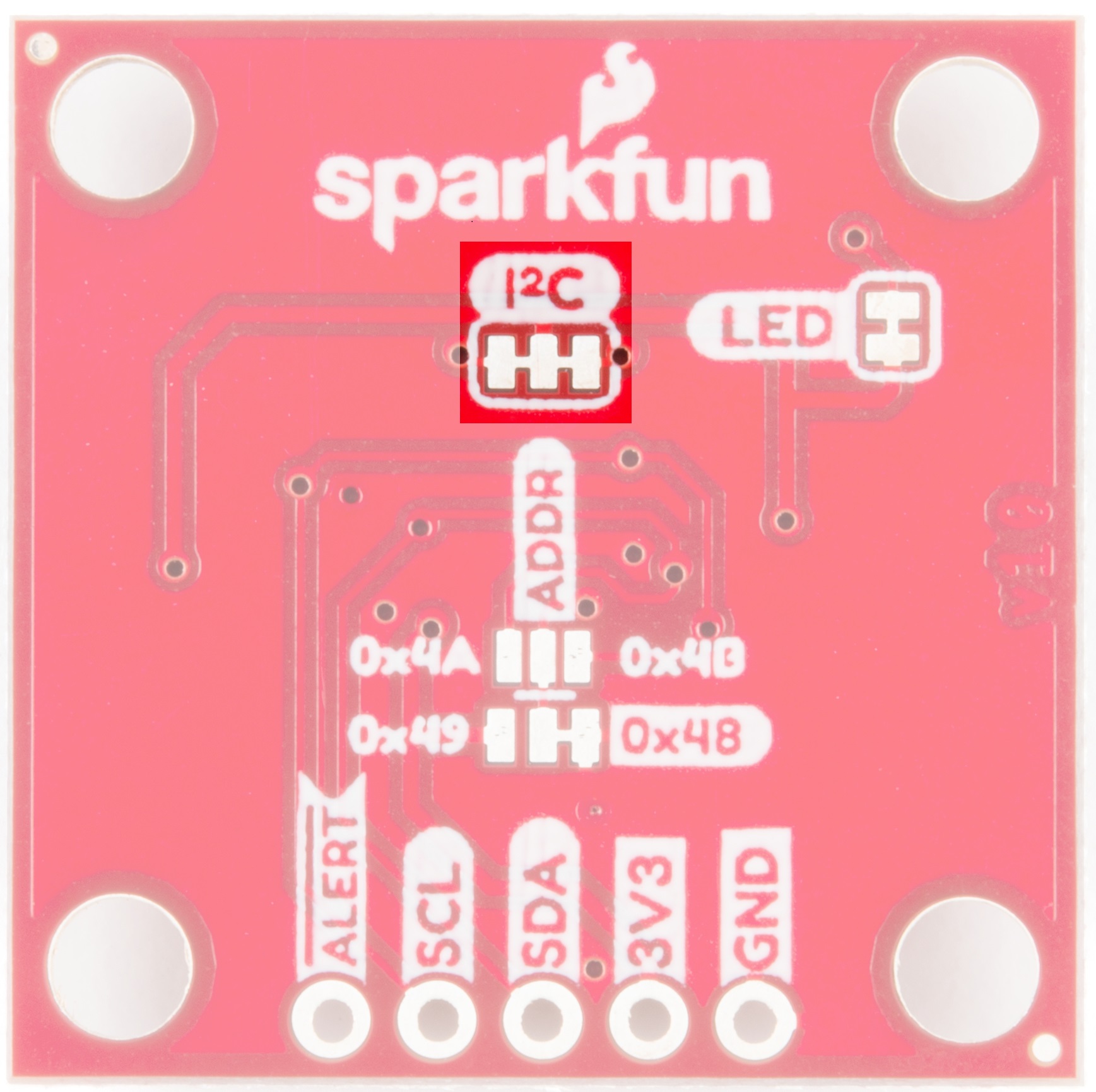
ADDR Jumpers
The default I2C address of the board is 0x48. To change the address, cut the jumper connecting the two pads closest to the 0x48 label. Soldering one of the center pads to one of the outer most pads will change the boards address to the matching label. The TMP102's address is determined by connecting the address pin directly to one of the following:
| ADDR | Address |
|---|---|
| GND | 0x48 |
| 3V3 | 0x49 |
| SDA | 0x4A |
| SCL | 0x4B |

LED Jumpers
Cutting this jumper will disable the Power LED on the front of the board.

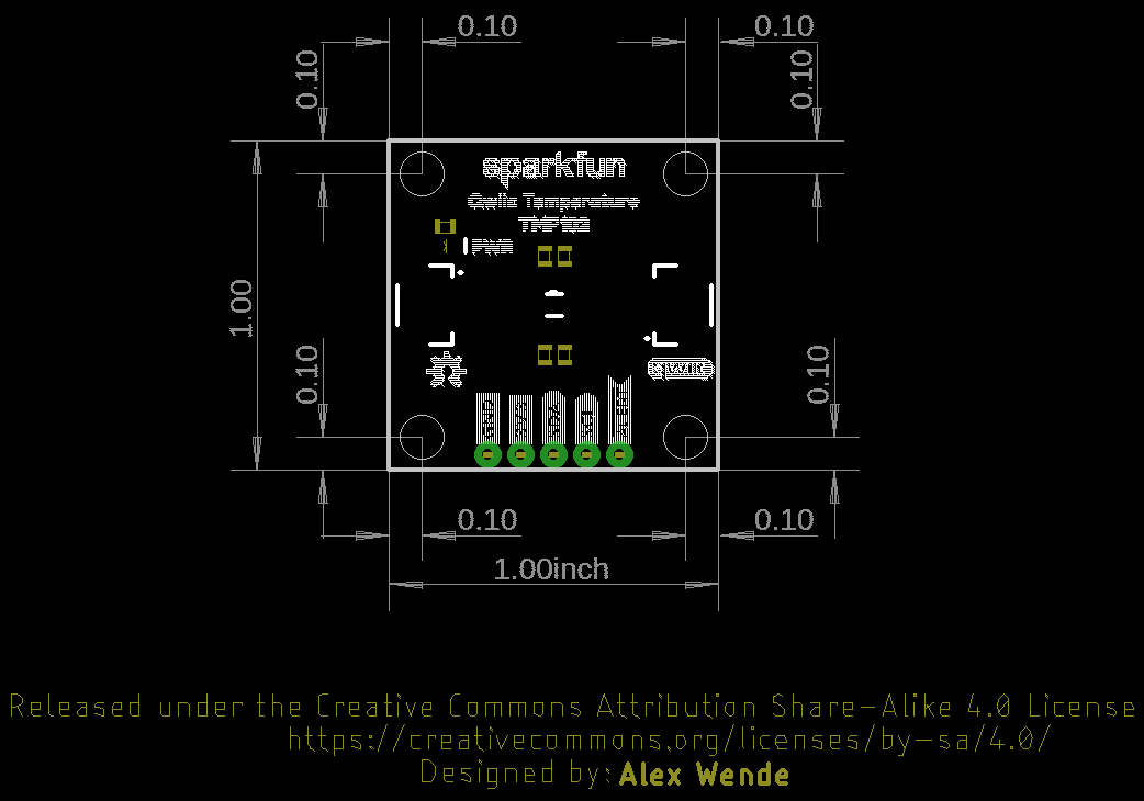
Board Dimensions
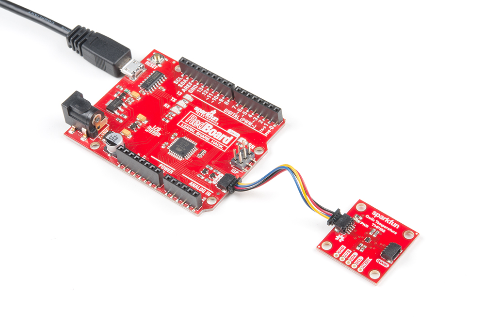
Hardware Assembly
With the Qwiic ecosystem, getting up and running is easy! Just plug one end of your Qwiic cable into your TMP102 sensor and the other into the Qwiic port on your RedBoard Qwiic. Voila! You're ready to sense some temperatures!
Software Setup and Programming
If this is your first time using Arduino, please review our tutorial on installing the Arduino IDE. If you have not previously installed an Arduino library, please check out our installation guide.
The Qwiic version of this board uses the same Arduino library as the original board. You can obtain this library through the Arduino Library Manager by searching for SparkFun TMP102. If you prefer downloading libraries manually, you can grab it from the GitHub Repository.
Once the library is installed, open Arduino, and expand the examples menu. You should see the TMP102 example.

TMP102 Library Overview
Main functions
These are functions used to read settings and temperatures from the sensor.
bool begin( uint8_t deviceAddress, TwoWire &wirePort )- Takes the device address and I2C bus as optional inputs. If left blank, this function uses the default address 0x48, and uses the Wire bus.float readTempC( void )- Returns the current temperature in Celsius.float readTempF( void )- Returns the current temperature in Fahrenheit.float readLowTempC( void )- Reads T_LOW register in Celsius.float readHighTempC( void )- Reads T_HIGH register in Celsius.float readLowTempF( void )- Reads T_LOW register in Fahrenheit.float readHighTempC( void )- Reads T_HIGH register in Fahrenheit.void sleep( void )- Put TMP102 in low power mode (<0.5 uA).void wakeup( void )- Return to normal power mode (~10 uA). When the sensor powers up, it is automatically running in normal power mode, and only needs to be used after *sleep()is used.bool alert( void )- Returns the state of the Alert register. The state of the register is the same as the alert pin.void setLowTempC(float temperature)- Sets T_LOW (in Celsius) alert threshold.void setHighTempC(float temperature)- Sets T_HIGH (in Celsius) alert threshold.void setLowTempF(float temperature)- Sets T_LOW (in Fahrenheit) alert threshold.void setHighTempF(float temperature)- Sets T_HIGH (in Fahrenheit) alert threshold.void setConversionRate(uint8_t rate)- Sets the temperature reading conversion rate. 0: 0.25Hz, 1: 1Hz, 2: 4Hz (default), 3: 8Hz.void setExtendedMode(bool mode)- Enable or disable extended mode. 0: disabled (-55C to +128C), 1: enabled (-55C to +150C).void setAlertPolarity(bool polarity)- Sets the polarity of the alert. 0: active LOW, 1: active HIGHvoid setFault(uint8_t faultSetting)- Sets the number of consecutive faults before triggering alert. 0: 1 fault, 1: 2 faults, 2: 4 faults, 3: 6 faults.void setAlertMode(bool mode)- Sets the type of alert. 0: Comparator Mode (Active from when temperature > T_HIGH until temperature < T_LOW), 1: Thermostat mode (Active from when temperature > T_HIGH until any read operation occurs.
Example Code
Once the library is installed, open the example code to get started! Make sure to select your board and COM port before hitting upload to begin experimenting with the temperature sensor.
language:c
/******************************************************************************
TMP102_example.ino
Example for the TMP102 I2C Temperature Sensor
Alex Wende @ SparkFun Electronics
April 29th 2016
~

This sketch configures the TMP102 temperature sensor and prints the
temperature and alert state (both from the physical pin, as well as by
reading from the configuration register.

Resources:
Wire.h (included with Arduino IDE)
SparkFunTMP102.h

Development environment specifics:
Arduino 1.0+

This code is beerware; if you see me (or any other SparkFun employee) at
the local, and you've found our code helpful, please buy us a round!

Distributed as-is; no warranty is given.
******************************************************************************/

// Include the SparkFun TMP102 library.
// Click here to get the library: http://librarymanager/All#SparkFun_TMP102

#include <Wire.h> // Used to establied serial communication on the I2C bus
#include <SparkFunTMP102.h> // Used to send and recieve specific information from our sensor

// Connections
// VCC = 3.3V
// GND = GND
// SDA = A4
// SCL = A5
const int ALERT_PIN = A3;

TMP102 sensor0;

void setup() {
  Serial.begin(115200);
  Wire.begin(); //Join I2C Bus

  pinMode(ALERT_PIN,INPUT);  // Declare alertPin as an input

  /* The TMP102 uses the default settings with the address 0x48 using Wire.

     Optionally, if the address jumpers are modified, or using a different I2C bus,
     these parameters can be changed here. E.g. sensor0.begin(0x49,Wire1)

     It will return true on success or false on failure to communicate. */
  if(!sensor0.begin())
  {
    Serial.println("Cannot connect to TMP102.");
    Serial.println("Is the board connected? Is the device ID correct?");
    while(1);
  }

  Serial.println("Connected to TMP102!");
  delay(100);

  // Initialize sensor0 settings
  // These settings are saved in the sensor, even if it loses power

  // set the number of consecutive faults before triggering alarm.
  // 0-3: 0:1 fault, 1:2 faults, 2:4 faults, 3:6 faults.
  sensor0.setFault(0);  // Trigger alarm immediately

  // set the polarity of the Alarm. (0:Active LOW, 1:Active HIGH).
  sensor0.setAlertPolarity(1); // Active HIGH

  // set the sensor in Comparator Mode (0) or Interrupt Mode (1).
  sensor0.setAlertMode(0); // Comparator Mode.

  // set the Conversion Rate (how quickly the sensor gets a new reading)
  //0-3: 0:0.25Hz, 1:1Hz, 2:4Hz, 3:8Hz
  sensor0.setConversionRate(2);

  //set Extended Mode.
  //0:12-bit Temperature(-55C to +128C) 1:13-bit Temperature(-55C to +150C)
  sensor0.setExtendedMode(0);

  //set T_HIGH, the upper limit to trigger the alert on
  sensor0.setHighTempF(82.0);  // set T_HIGH in F
  //sensor0.setHighTempC(29.4); // set T_HIGH in C

  //set T_LOW, the lower limit to shut turn off the alert
  sensor0.setLowTempF(81.0);  // set T_LOW in F
  //sensor0.setLowTempC(26.67); // set T_LOW in C
}

void loop()
{
  float temperature;
  boolean alertPinState, alertRegisterState;

  // Turn sensor on to start temperature measurement.
  // Current consumtion typically ~10uA.
  sensor0.wakeup();

  // read temperature data
  temperature = sensor0.readTempF();
  //temperature = sensor0.readTempC();

  // Check for Alert
  alertPinState = digitalRead(ALERT_PIN); // read the Alert from pin
  alertRegisterState = sensor0.alert();   // read the Alert from register

  // Place sensor in sleep mode to save power.
  // Current consumtion typically <0.5uA.
  sensor0.sleep();

  // Print temperature and alarm state
  Serial.print("Temperature: ");
  Serial.print(temperature);

  Serial.print("\tAlert Pin: ");
  Serial.print(alertPinState);

  Serial.print("\tAlert Register: ");
  Serial.println(alertRegisterState);

  delay(1000);  // Wait 1000ms
}
Troubleshooting
If your product is not working as you expected or you need technical assistance or information, head on over to the SparkFun Technical Assistance page for some initial troubleshooting.
If you don't find what you need there, the SparkFun Forums are a great place to find and ask for help. If this is your first visit, you'll need to create a Forum Account to search product forums and post questions.
Resources and Going Further
Want more information on the Qwiic TMP102? Check out these links!
- Schematic (PDF)
- Eagle Files (ZIP)
- Datasheet (PDF)
- Qwiic Info Page
- Arduino Library
- GitHub Hardware Repo
- SFE Product Showcase
Need more inspiration? Check out our Qwiic line of products: