SparkFun Qwiic Button Hookup Guide
 El Duderino
Hardware Overview
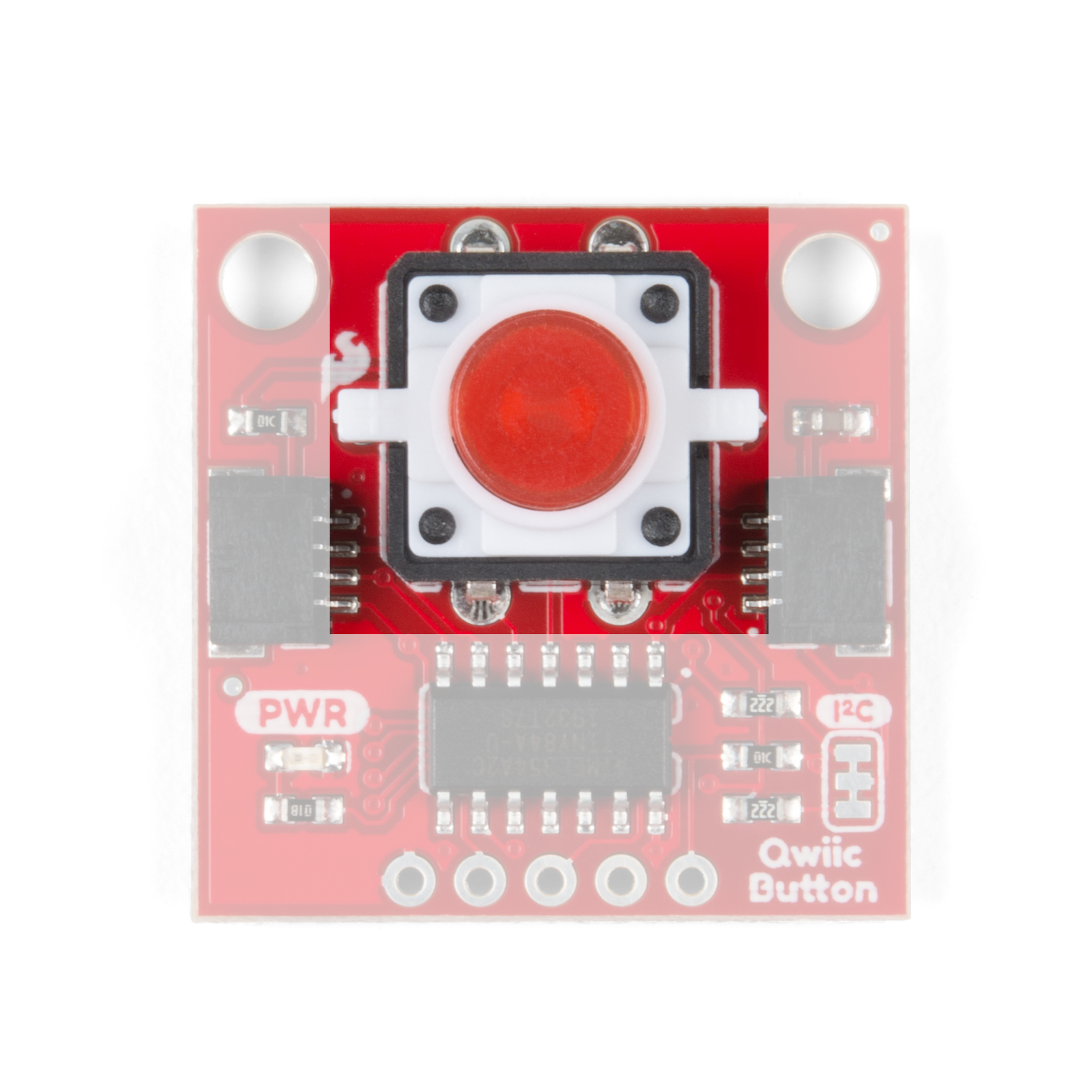
Tactile Button
This is a standard pushbutton with a built in red or green LED depending in which version you have. The LED's anode (positive pin) is connected to an I/O pin on the ATtiny84 so you can turn it on and off as well as control the brightness. If you have the Qwiic Button Breakout, you can choose your own color of button from the selection listed in the Introduction of this guide or any tactile button that fits the footprint on the breakout.
 |
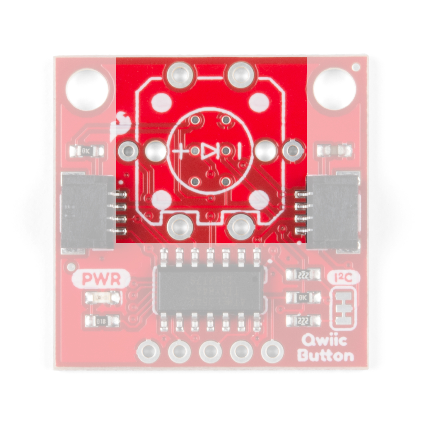 |
| Red Tactile Button | Button Footprint |
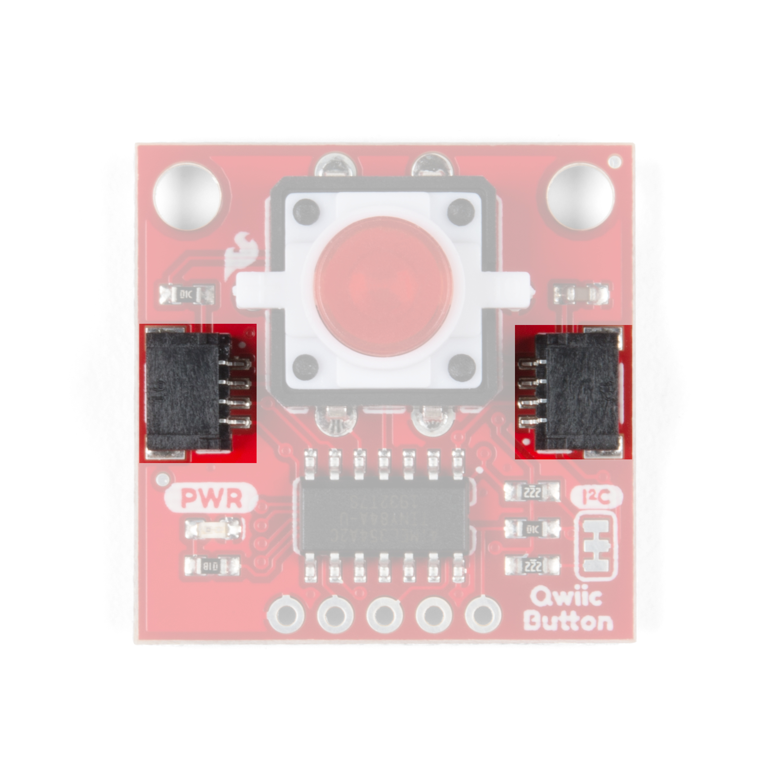
Qwiic and I2C Interface
The easiest way to use the Qwiic Button is with the Qwiic connect system. Simply plug in a Qwiic Cable to start talking to it.
 |
 |
| Qwiic Connectors | I2C Pins |
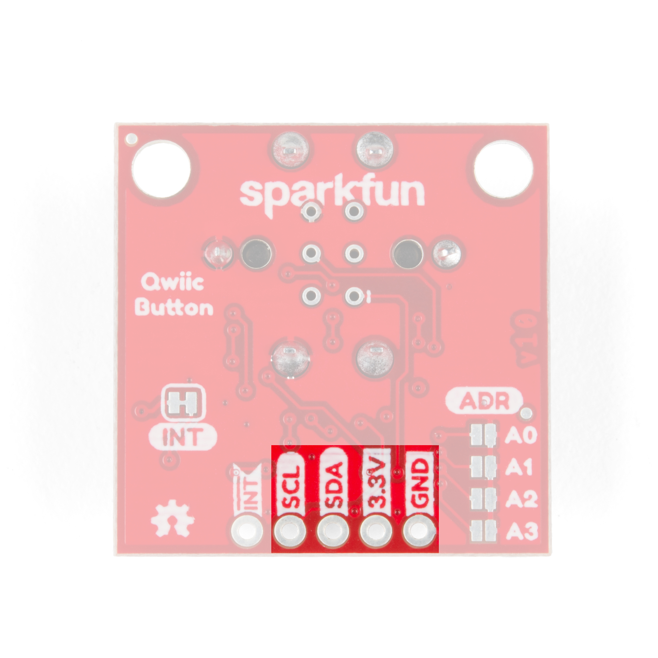
Alternatively, you can solder to the I2C pins broken out on the board.
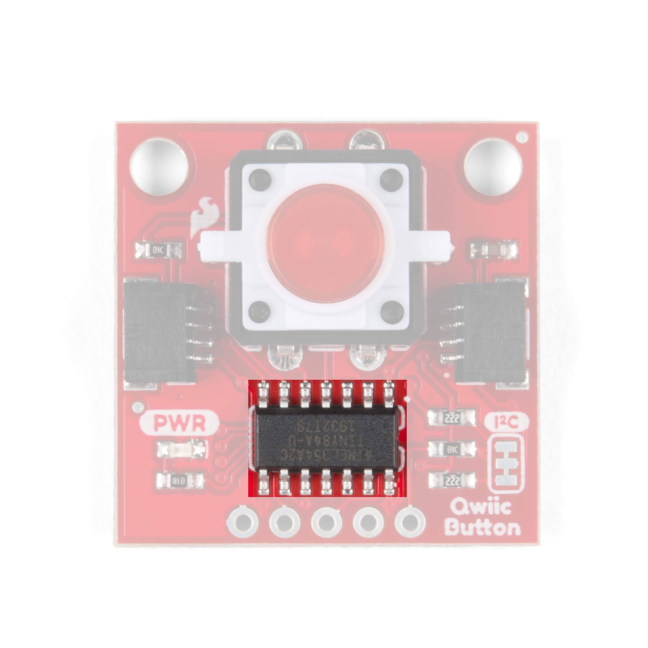
ATtiny84
The ATtiny84 has pre-installed firmware to handle the various functions of the Qwiic Button. It acts as an intermediary device to send and receive I2C data for things like button presses, clicks, the FIFO queue and it allows you to set a custom I2C address for the Qwiic Button. If you would like, you can modify the firmware on the Qwiic Button using the 2x3 pins on the back of the board. The firmware can be found in the Hardware GitHub Repository and if you need help programming the ATTiny84, check out this tutorial.
Jumpers
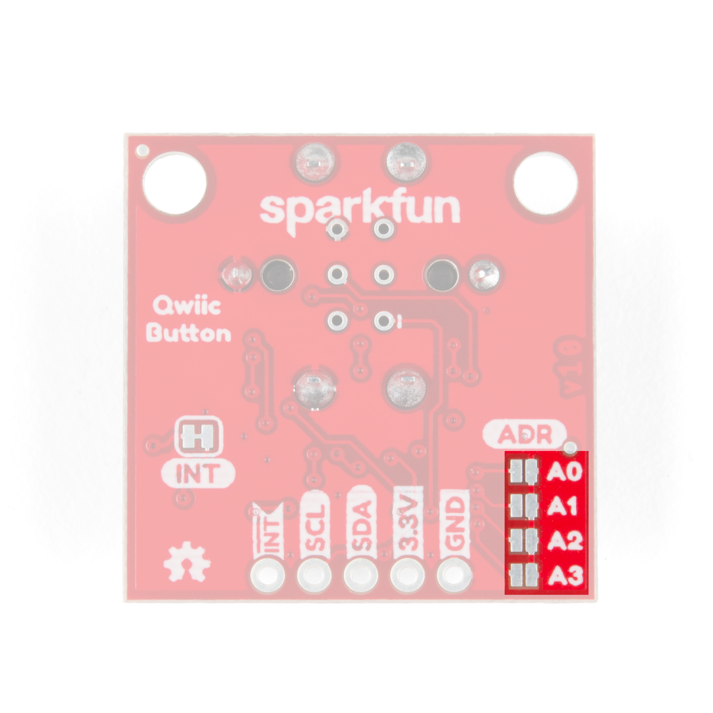
I2C Address Jumpers
There are four solder jumpers on the board (labeled A0, A1, A2 and A3) you can close to set the I2C address. The firmware reads the logic of each address pin so, by closing multiple jumpers, you can modify the Qwiic Button with up to sixteen unique addresses! If you do not want to use the address pins, the address can also be configured using the ChangeI2CAddress Example from our Arduino Library.
- All Open: Factory or User Set I2C Address: 0x6F (Factory Set) or 0x## (User Set)
- Alternate Address Jumpers: Closing an address jumper sets the pin LOW. On boot-up, the firmware checks the state of these four pins and adjusts the I2C address following this logic:
0b0110,A3,A2,A1,A0For example, with both A0 and A1 jumpers closed, (A0 = 0, A1 = 0, A2 = 1, A3 = 1) the I2C address of the Qwiic Button is set to 0x6C (0b01101100). Check out the table below for a full list of all the I2C addresses and the jumper logic used to set the address.
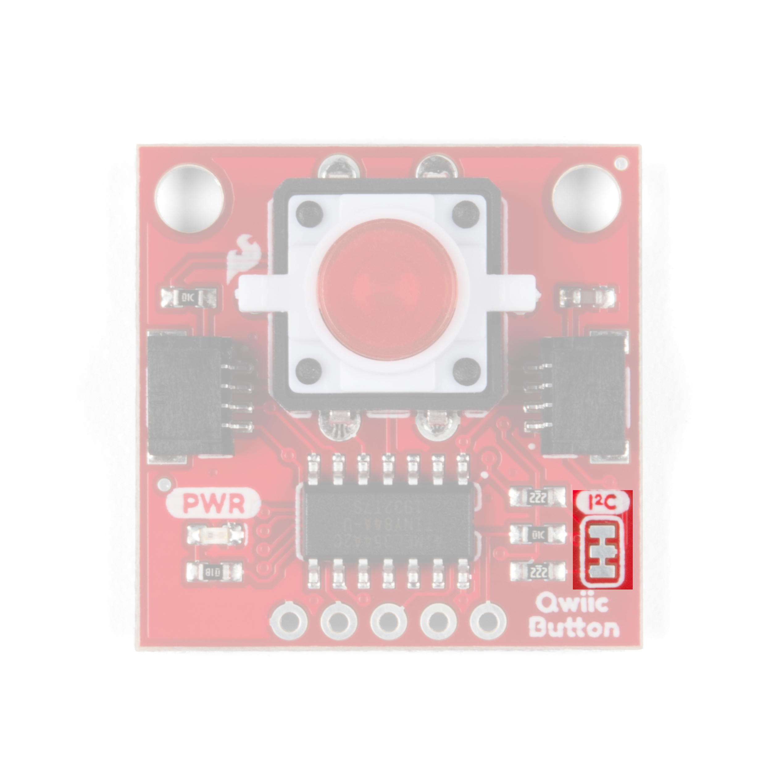
I2C Pull-Up Resistors
Severing the trace on the I2C jumper will remove the 2.2kΩ pull-up resistors from the I2C bus. If you have many devices on your I2C bus you may want to open these jumpers by severing the trace in between the pads.
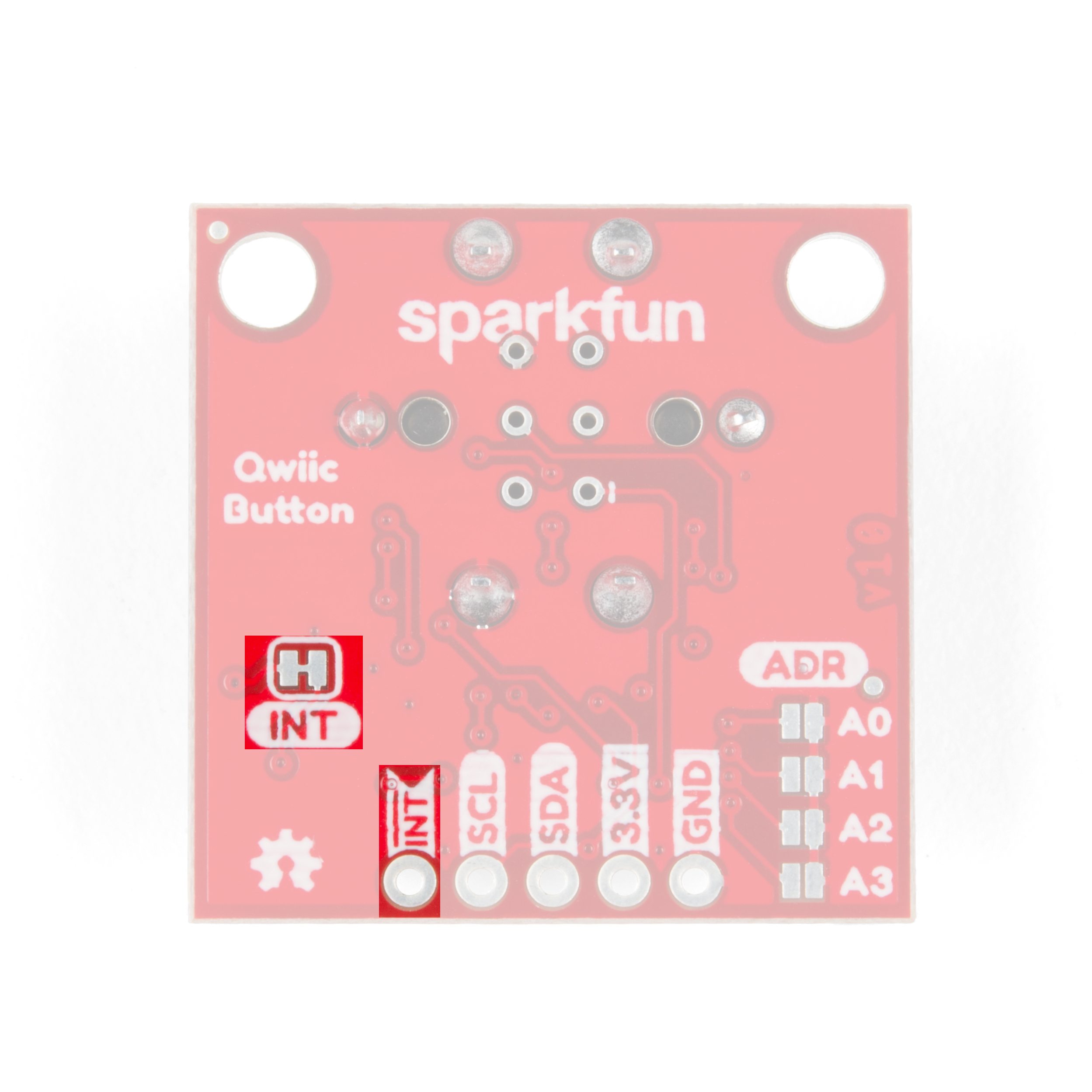
Interrupt Pin
The Interrupt Pin can be used to trigger events on your microcontroller. It is active LOW and can be configured to activate on either a button press (held down) and click (press-and-release). By default, the Interrupt Pin is pulled to 3.3V via a 10K resistor through this jumper. Just like the I2C pull-up resistors, you can open it by severing the trace in between the pads. This may come in handy for low-power projects that do not require the Interrupt Pin.
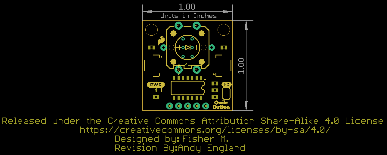
Board Dimensions
The breakout board is the standard Qwiic size of 1" x 1" and has two mounting holes that fit a standard 4-40 screw.