SparkFun Pro nRF52840 Mini Hookup Guide
Introduction
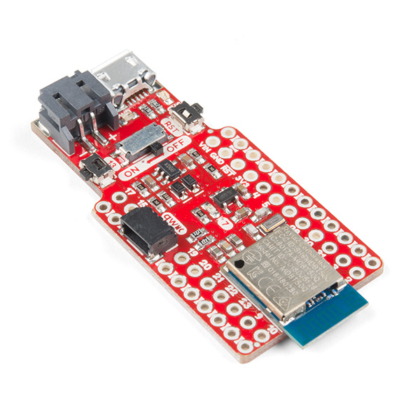
The SparkFun Pro nRF52840 Mini is a breakout and development board for Nordic Semiconductor's nRF52840 -- a powerful combination of ARM Cortex-M4 CPU and 2.4 GHz Bluetooth radio. With the nRF52840 at the heart of your project, you'll be presented with a seemingly endless list of project possibilities.
Our "mini" development board for the nRF52840 breaks out most, critical I/O pins while maintaining a small footprint. It features a USB interface (using the nRF52840's native USB support), which can be used to program, power, and communicate with the chip. Also included are a LiPo battery charger, qwiic connector, on/off switch, reset switch, and a user LED/button.
The board comes pre-programmed with a USB bootloader. You can develop programs for the nRF52840's Cortex-M4 using either Arduino, Circuit Python, or C (using Nordic's nRF5 SDK), and load that compiled code on using a USB serial or mass-storage interface.
Covered in This Tutorial
This tutorial is designed to introduce you to the nRF52840 and the hardware features of our Pro nRF52840 Mini Breakout. It will help you assemble the board, and then send you on to the software-development method of your choice.
Make sure to check out the Software Development Guides section, which splits into Arduino, Circuit Python, or C (Nordic SDK) development guides.
Required Materials
To follow along with this tutorial, you will need the following materials. You may not need everything, depending on what you already have. Add it to your cart, read through the guide, and adjust the cart as necessary.
Tools
You will need a soldering iron, solder, and general soldering accessories to solder your headers to your nRF52840.
Weller WLC100 Soldering Station
TOL-14228As you look to add more components to your nRF52840 breakout, make sure you check out our line of qwiic boards. The I2C-based qwiic interface is a quick way to prototype and test a huge variety of sensors and ouptuts.
Suggested Reading
This tutorial builds on a variety of electronics, programming, and engineering concepts. If any of the subjects of these tutorials sound foreign to you, consider checking them out before continuing on:
Serial Communication
Logic Levels
Using the Arduino Pro Mini 3.3V
Bluetooth Basics
The nRF52840
Lets quickly overview Nordic's nRF52840. Its list of features is exhaustingly-awesome. Just to top off a few of our favorite features, there's:
- ARM Cortex-M4 CPU with floating point unit (FPU)
- 1MB internal Flash -- For all of your program, SoftDevice, and file-storage needs!
- 256kB internal RAM -- For your stack and heap storage.
- Integrated 2.4GHz radio with support for:
- Bluetooth Low Energy (BLE) -- With peripheral and/or central BLE device support
- Bluetooth 5 -- Mesh Bluetooth!
- ANT -- If you want to turn the device into a heart-rate or exercise monitor.
- Nordic's proprietary RF protocol -- If you want to communicate, securely, with other Nordic devices.
- Every I/O peripheral you could need
- USB -- Turn your nRF52840 into a USB mass-storage device, use a CDC (USB serial) interface, and more. This is a big add compared to the nRF52832!
- UART -- Serial interfaces with support for hardware flow-control if desired.
- I2C -- Everyone's favorite 2-wire bi-directional bus interface
- SPI -- If you prefer the 3+-wire serial interface
- Analog-to-digital converters (ADC) -- Eight pins on the nRF52840 Mini Breakout support analog inputs
- PWM -- Timer support on any pin means PWM support for driving LEDs or servo motors.
- Real-time clock (RTC) -- Keep close track of seconds and milliseconds, also supports timed deep-sleep features.
- Peripheral-multiplexing -- (Nearly) any pin can support any of the above features!
USB
Nordic's nRF52840 builds on their nRF52832 by adding a heap (pun intended) of memory, but the most significant addition is that of built-in support for Full-Speed USB 2.0 interfaces.
The USB interface supports any USB device class you can imagine, including communication device class (CDC, USB-to-serial), mass-storage device (MSC, removable flash-drives), human-interface device (HID, keyboard/mouse), and audio.
On-chip USB support means, most significantly, that a USB bootloader can be built into the chip. No more USB-to-serial converters required to load compiled code onto your chip! For more information on the USB bootloader pre-programmed onto the SparkFun Pro nRF52840 Mini Breakout, check out the Using the Bootloader section.
I/O Features
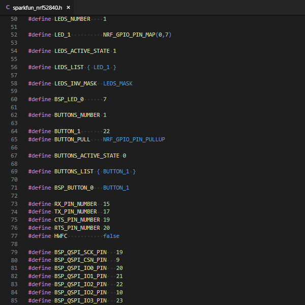
Coming from the world of AVR's like the Arduino Uno's ATmega328 -- or even more modern processors like the SAMD21 -- one of the coolest features of the nRF52840's Cortex-M4 is its expansive pin multiplexing capability. Just about any pin can support any peripheral. Want UART0's RX to be on pin P0.02? You got it. Need to flip RX and TX? Just a quick definition change.
In the software development guides, we'll provide hardware definitions for "standard" I/O interfaces, but we'll also demonstrate how to tweak these definitions, so you can bend the nRF52840 to your whim.
2.4GHz Radio
The nRF52840's most unique feature is it's integrated 2.4GHz radio. This radio is most commonly used as a Bluetooth Low-Energy (BLE) interface, but it can also be used for Bluetooth 5 (a meshed, long-range extension of the Bluetooth spec), ANT (a proprietary network usually used for heart-rate monitors), or Nordic's proprietary 2.4GHz interface.
A Note on SoftDevices
To use the radio for any of the Nordic nRF52840's 2.4GHz RF interfaces -- Bluetooth, proprietary or otherwise -- you'll need to load a SoftDevice onto your nRF52840.
A SoftDevice is a "precompiled and linked binary software implementing a wireless protocol." It provides easy access to a Bluetooth or other 2.4GHz radio stack. They are, unfortunately, closed-source, but they do reduce complexity and compile-time for your application.
We load the S140 v6.1.1 SoftDevice onto the Pro nRF52840 Mini Breakout in production here at SparkFun. The S140 SoftDevice supports Bluetooth Low Energy applications.
New SoftDevices can be loaded onto your board via the USB bootloader, but it's important to know which SoftDevice is currently loaded.
Hardware Overview
With the nRF52840 overviewed, let's take a quick look at the features of our board equipped with the Cortex-M4/BT SoC:
Raytac MDBT50Q-P1M Module
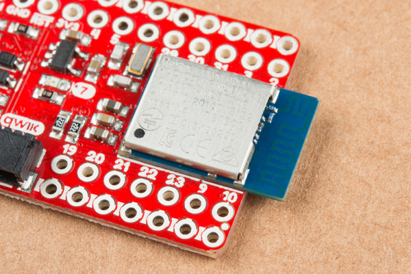
The Pro nRF52840 Mini Breakout actually features a Raytac MDBT50Q-P1M module. This module connects the nRF52840 to an trace antenna, fits the IC into an FCC-approved footprint, and also includes a lot of the decoupling and timing mechanisms (i.e. 32 MHz crystal) that would otherwise be required for a bare nRF52840 design.
For more information on the MDBT50Q-P1M, check out the datasheet.
SparkFun Pro nRF52840 Mini Pinout
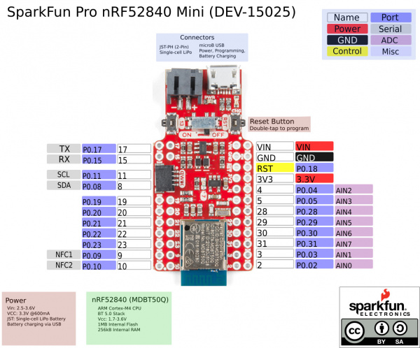
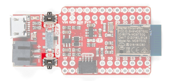
Most pin breakouts on the SparkFun Pro nRF52840 Mini are general purpose I/O pins (GPIO). As mentioned in the last section, GPIO on the nRF52840 can be muxed to just about any functionality your project requires.
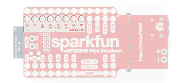
The analog-to-digital converter (ADC) pins are the only ones you may need to put extra focus on. These pins are broken out and available on GPIO pins 2-5 and 28-31. You'll find these pins on one side of the board; they're helpfully highlighted on the bottom-side silk.
The footprint of the SparkFun Pro nRF52840 Mini nearly matches that of the SparkFun Arduino Pro Mini. You'll find power pins in the expected spot. And GPIO — aside from those covered by the qwiic connector — can be used for any purpose (UART, I2C, SPI) that those of the Arduino Pro Mini could.
There are breakouts for the 3.3V regulator output (3V3) and input (VIN). Check out the next section for more information on these pins.
Finally, you'll find an array of ground breakouts on the outside edges of the board. These are covered -- as well as the board fab will allow -- with white silkscreen.
Powering the nRF52840 Breakout
The breakout's micro-B USB interface can be used to both power and program the breakout. The supply-end of your micro-B cable can be either a computer or a USB wall-adapter.
The nRF52840 consumes a very low amount of power -- less than 20mA on normal, radio-transceiving operation. Any computer USB interface should be able to reliably power the module.
Alternatively, the nRF52840 Mini breakout's 3V3 and VIN pins can be used to directly power the board. Power to the VIN pin should be regulated to somewhere between 3.3V and 5.5V, as this supplies the low-dropout 3.3V regulator. If you want to bypass the regulator, a voltage between 2.5-3.6V can be applied to the 3.3V pin to supply power to the nRF52840 module.
LiPo Charger
In lieu of (or in addition to) the USB supply, a Lithium-Polymer (LiPo) battery can be used to supply the breakout.
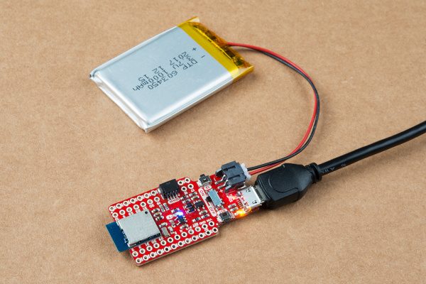
A smart-power-selection circuit will ensure that if both USB and LiPo are connected, power to the nRF52840 and its components will be supplied by the USB interface, otherwise LiPo power will be used to supply the system. The USB interface can also be used to charge the LiPo.
ON/OFF Switch
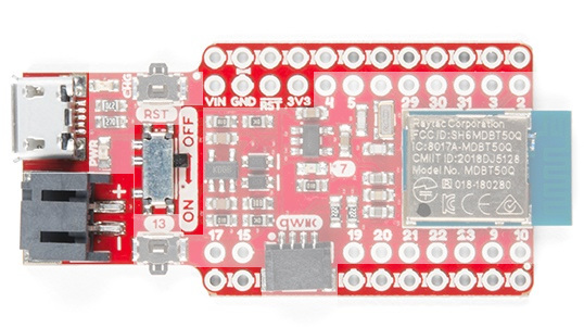
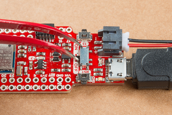
An SPDT on/off switch is populated on the board. This switch controls the enable input on the 3.3V regulator, so any power supplied on the VIN-side of the board (USB and LiPo included) will be regulated by this switch.
The switch, initially, seems oddly placed toward the inside of the board. This helps maintain the small form-factor and ensures spurious swats don't accidentally cycle your project's power.
If you can't get a fingernail into the narrow gap between the switch and components, a pair of tweezers may do the trick.
Reset and Pin-13 Buttons
Reset and user-programmable momentary SPST buttons are provided on either sides of the on/off switch. These buttons play a critical purpose in triggering the bootloader, which we'll delve into more in the next section. In your application, the pin-13 button can be used for any purpose.
Both of these buttons are pulled high, so their signal will go low when the button is actuated.
LEDs: Power, Charge, and Pin 7
The board is equipped with three LEDs. Their color and feature-indications are:
| LED Label | Color | Purpose |
|---|---|---|
| PWR | Red | 3.3V power indication. Inidicates the nRF52840 is powered. |
| CHG | Yellow | LiPo battery charge indicator. Illuminates when the battery is charging. |
| 7 | Blue | nRF52840 pin 7. Active-high. Will blink in bootloader mode. |
Qwiic Connector
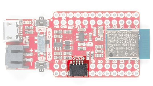
A qwiic connector is provided on the board, with a pair of the nRF52840's I2C-capable pins connected to SDA and SCL.
The nRF52840's P0.11 pin is connected to the qwiic connector's SCL and P0.08 is connected to SDA. See the pinout image here for quick reference.
 |
 |
| Qwiic Connector | Qwiic Connector Pins P0.11 and P0.08 |
SWD Interface
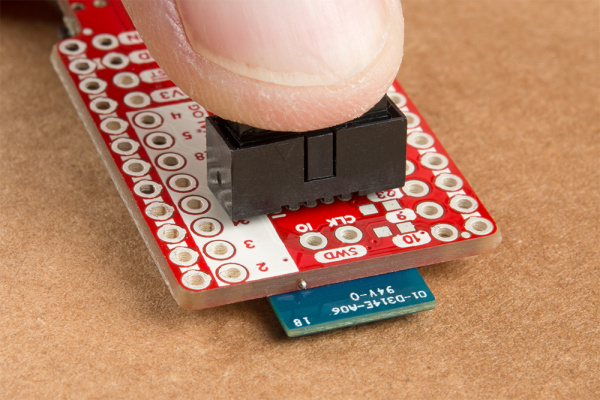
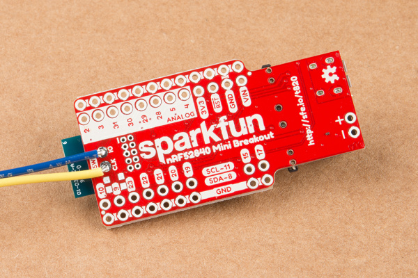
If you ever want to bypass the bootloader (or knock-on-wood you brick it), the nRF52840's single-wire debug (SWD) pins are broken out on the bottom of the board.
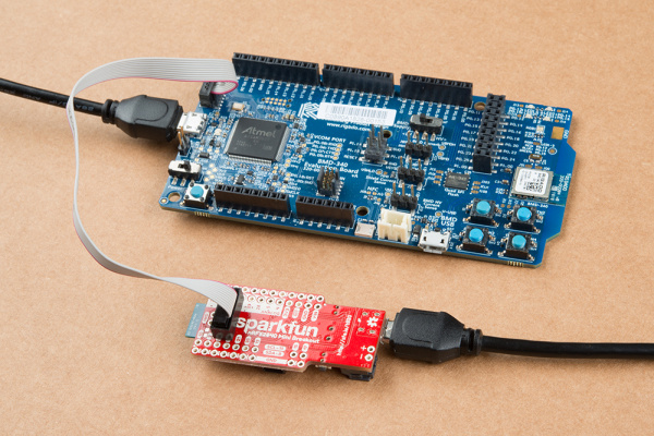
They may be difficult to solder to, as the module blocks the other side, but they can be held in place while you quickly program. A 10-pin, 2x5, 0.5" pitch header, for example, can be angled, and pressure-fit into the 10-pin, 2x5 Cortex-debug connector. Make sure you match up the debug cable's pin-1 indicator to the small silkscreen pin-1 indicator on the board! In the following example, a polarized female header was used to connect the cable to the board.
You can then use a programming tool, like Nordic's nRF52840 DK to flash new firmware onto your nRF52840 via SWD.
The SWD's IO and CLK pins can also be soldered to using relatively high-gauge wire, and routed to the programming interface of your choice if you prefer.
Hardware Assembly
Because the Pro nRF52840 Mini Breakout is a more advanced development platform, we'll leave most of the hardware hookup to you. Here are a few quick tips-and-tricks, though:
Soldering the Breakout
You will need to solder something to the I/O and/or power pins to connect them to other components. New to soldering? No worries! Check out our through-hole soldering tutorial.
How to Solder: Through-Hole Soldering
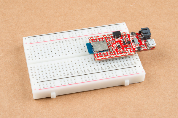
We recommend soldering in either male header pins or female header sockets, but what you solder into these pins ultimately depends on your application.
Each of the nRF52840's ground (GND) and I/O/power headers are 12-pins, with the exception of...
That Gap in the I/O Header...
We hope the addition of a qwiic connector provides easy access to a huge library of sensors, displays, and output-controllers, but, admittedly, the connector's placement does mess with the breakout's solder-ability.
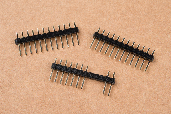
If you have a 12-pin header that you'd like to solder into these breakout pins, either cut or "push-out" the 3rd, 4th, and 5th (1-indexed) pins of the header.
Otherwise you can cut two separate strips of 7- and 2-pin headers.
Using the Bootloader
Hopefully (unless you really need a debug interface) you'll never have to touch those SWD pins on the bottom side of the nRF52840 Breakout. The pre-programmed USB bootloader should have all of your programming bases covered.
The USB bootloader programmed on this board should provide support for programming via either USB serial (CDC), DFU (device firmware upgrade) or mass-storage device (MSD). So you can either automate your programming via a serial-like interface or drag a pre-compiled application onto your nRF52840's removable drive.
The bootloader that ships on this board is heavily based on Adafruit’s nRF52 Bootloader. This is an extremely well-designed UF2, CDC, and DFU bootloader that provides extensive bootloading support to Nordic’s nRF52 (nRF52840 and nRF52832) products.
Software Tools Required
After you've compiled your nRF52840 application, you'll need one of two software tools to upload it to the chip via the USB bootloader. Both applications are compatible across all platforms.
adafruit-nrfutil and Python 3
Nordic's nrftuil is a Python-based tool for packaging device firmware updates (DFU) and updating a nRF chip with that package over either serial or Bluetooth. adafruit-nrfutil is derived from Nordic's original version of the software. It updates nrfutil to be Python 3-based, and provides DFU support for a variety of boards equipped with their nRF52 bootloader.
adafruit-nrfutil is used to update code on your nRF52840 with the serial bootloader.
To install adafruit-nrfutil, you'll first need to download and install Python 3. (If you have Python 2.7 installed, you'll still need Python 3 to install adafruit-nrfutil.)
Once you have Python 3 installed, the easiest way to install adafruit-nrfutil is with PyPI:
pip3 install --user adafruit-nrfutil uf2conv.py (and Python Too)
In addition to the USB serial bootloader, the nRF52840 also includes a UF2 bootloader. This bootloader turns the nRF52840 into a USB mass-storage device, and allows you to simply drag a compiled file onto the device to program it.
If you'd like to take advantage of the nRF52840's UF2 bootloader, you'll need another Python-based tool: uf2conv.py. This Python script transforms a compiled ".hex" binary file to a UF2-compatible ".uf2" file.
You can grab the uf2conv.py script by downloading or cloning the Microsoft UF2 GitHub Repository.
To convert a compiled hex file to uf2, a command like...
python uf2conv.py -f 0xADA52840 -c -o _build/nrf52840_xxaa.uf2 _build/nrf52840_xxaa.hex ...should do the trick.
Entering the Bootloader
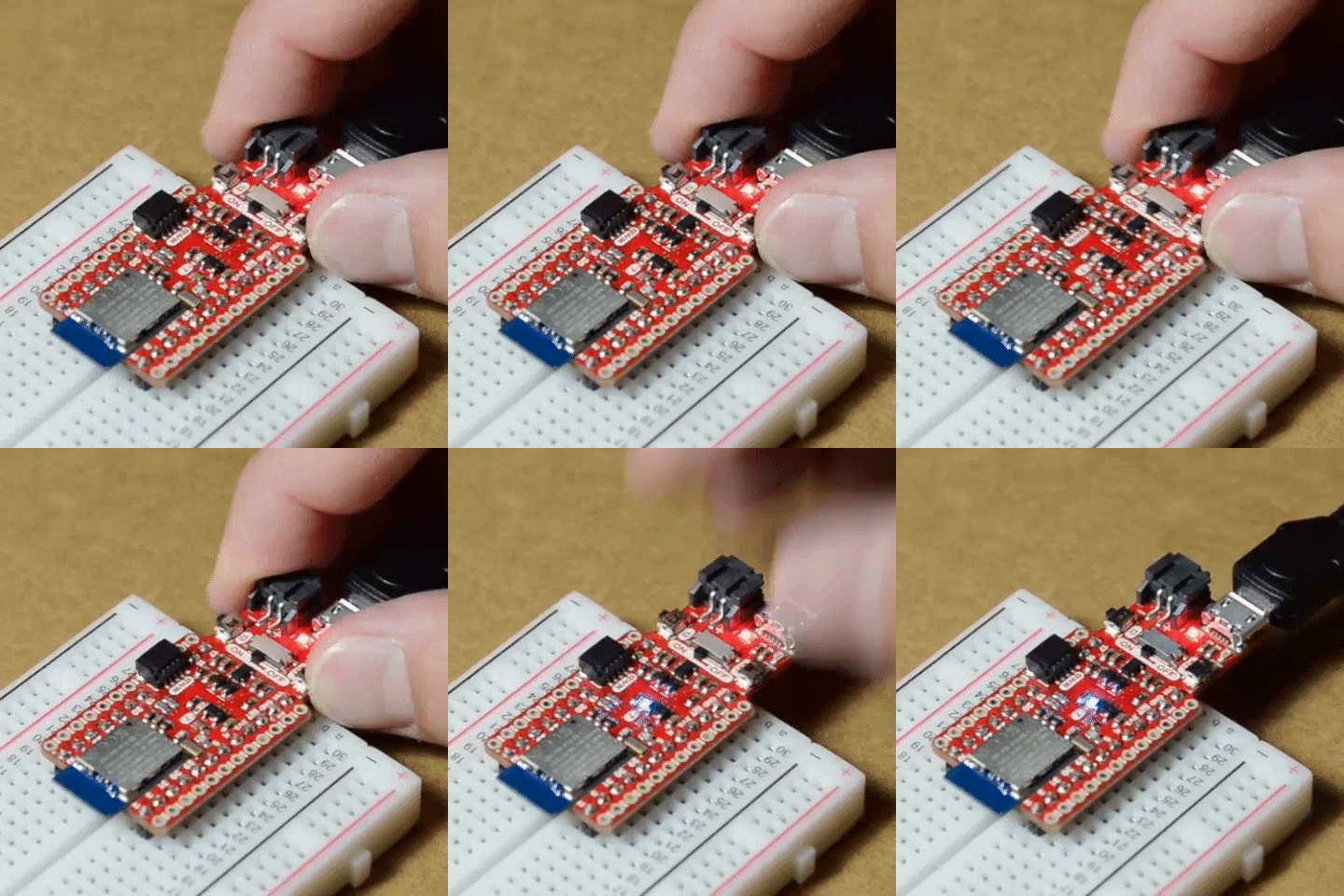
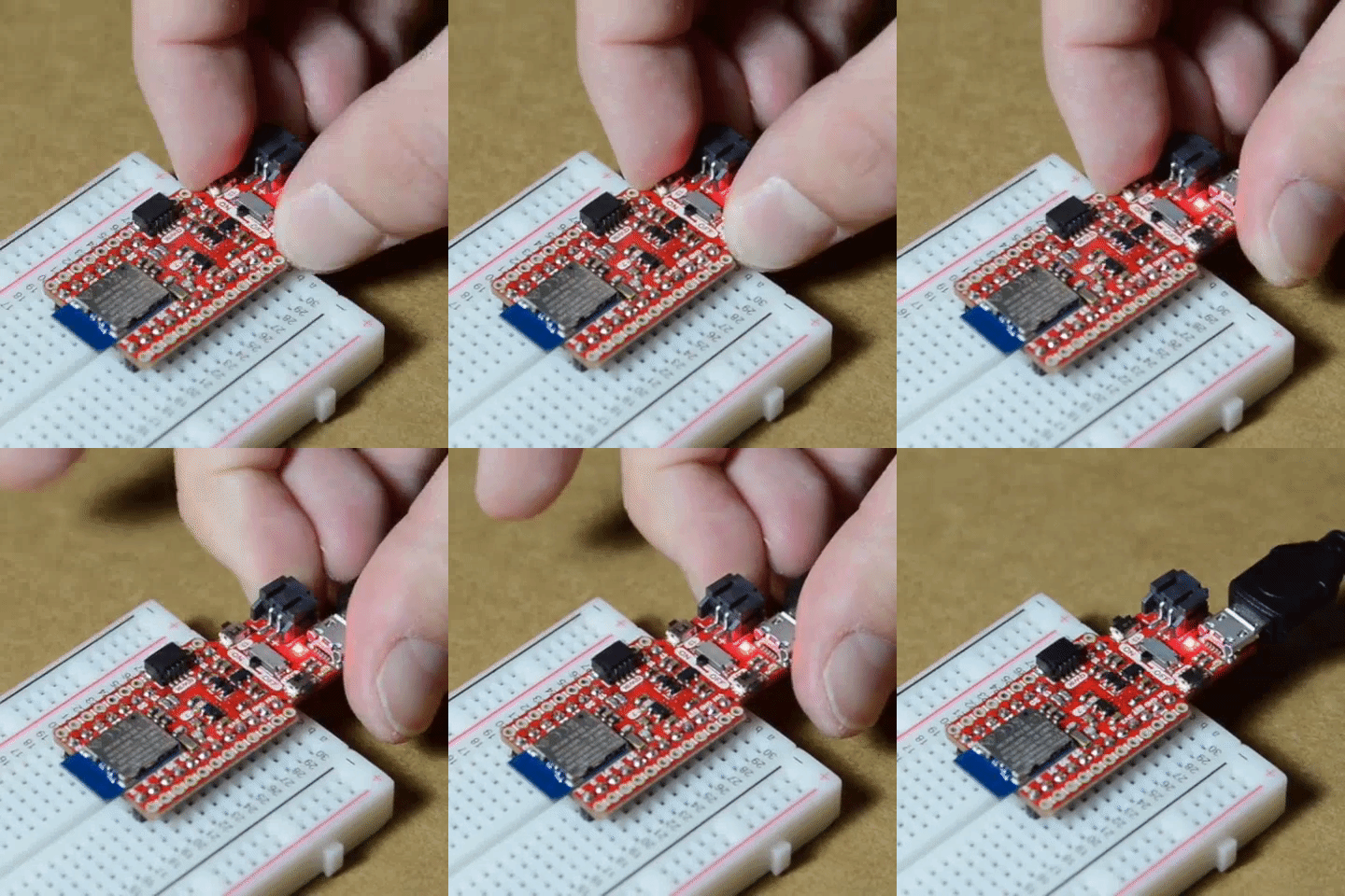
To get into bootloader mode manually you'll need to use one or both of the reset and pin-13 buttons. You can either double-tap the reset button.
Or reset while holding down the pin-13 button:
Either reset method will work. Bootloader mode is indicated by a flashing blue pin 7 LED. You should also notice a removable drive and USB serial port enumerate on your computer.
Factory Resetting
If your nRF52840 application isn't quite working as expected, you can wipe it out and return safely to bootloader mode. To perform a factory reset ground pin 2 while resetting the board.
Software Development Guides
Once you've set up your nRF52840's hardware and gotten comfortable with the USB bootloader, you're ready to begin developing applications!
There are three potential approaches to nRF52840 software development: Arduino and CircuitPython can provide a beginner-friendly approach while development in C with Nordic's nRF5 SDK (software development-kit) provides extensive access to all Nordic libraries and components.
If you're more comfortable in the Arduino and/or Python worlds, consider heading over to the nRF52840 Development with Arduino and/or CircuitPython tutorial as you continue your nRF52840 development.
nRF52840 Development with Arduino and CircuitPython
If you're interested in getting the most out of your nRF52840, at the cost of a bit more time getting comfortable with new API's, check out the nRF52840 Advanced Development With the nRF5 SDK tutorial.
nRF52840 Advanced Development With the nRF5 SDK
Resources and Going Further
Thanks for checking out the SparkFun Pro nRF52840 Mini Breakout! We're excited to see what amazing projects are created with the powerful Bluetooth/microcontroller combination.
For more documentation, be sure to check out the software development guides above. You may also find these resources handy:
- Hardware
- Schematic (PDF) -- PDF of the Pro nRF52840 Mini Breakout
- Eagle Files (ZIP) -- v10 Eagle PCB Design Files
- Graphical Datasheet (PDF) -- Graphical Datasheet PDF File
- Raytac MDBT50Q Datasheet
- SparkFun Pro nRF52840 Mini Breakout GitHub Respository
- Software
- Bootloader Source Code
- Nordic nRF5 SDK -- Nordic's nRF5 Software Development Kit -- software development environment for nRF52's.
- Arduino Core for nRF52 Boards -- Adafruit's Arduino core with support for nRF52 boards.
- CircuitPython nRF Port -- Adafruit's port of CircuitPython for nRF52 boards.
For more tutorials, more to learn, and more project-inspiration, check out these related tutorials:
