nRF52840 Development with Arduino and CircuitPython
 jimblom
 Introduction
Whether you're a novice programmer learning how to program or a seasoned expert looking for a quick rapid-prototyping development environment, Arduino and CircuitPython can be a great choice for programming environments/languages. Pairing those simple programming languages with a powerful microcontroller, like the nRF52840 takes them to an entirely new level -- a level with Bluetooth capability!
In this tutorial we'll demonstrate how to equip your nRF52840 and development computer with the firmware and software required to develop in either Arduino or CircuitPython. Both of these languages support digital I/O in/out, analog inputs, serial buses, and, most key to the nRF52840, support for Bluetooth Low Energy (BLE).
Required Materials
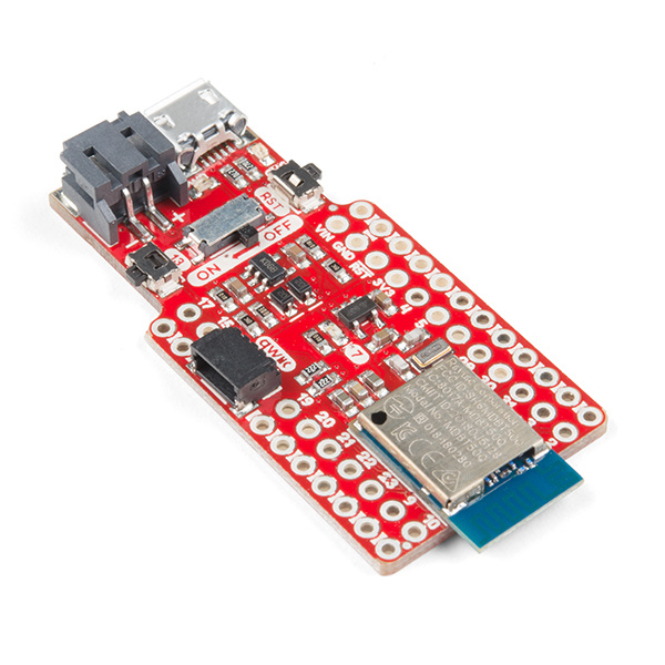
We'll be mostly focusing on using these programming tools on the SparkFun Pro nRF52840 Mini, but any other nRF52840 should be adaptable. The only caveat is the Adafruit nRF52840 Bootloader should be installed on the nRF52840.
Suggested Reading
If you haven't read through it already, we recommend following along with our SparkFun Pro nRF52840 Mini Hookup Guide before continuing on. This tutorial will familiarize you with the hardware features of the board as well as the intricacies of the DFU/UF2 bootloader.
SparkFun Pro nRF52840 Mini Hookup Guide
Arduino Installation
With the Arduino Board Manager, installing new board support within your Arduino IDE is a breeze! There will be one extra step to install the recommended support for the SparkFun Pro nRF52840 Mini, however.
Installing the Arduino Core for nRF52 Boards
Adafruit, who have done an amazing job developing their nRF52 Arduino core for the nRF52832, have been extending their support to the nRF52840.
To install the nRF52 Arduino Core:
- Open the Arduino IDE (must be v1.6.12 or later)
- Navigate to Preferences
- In the "Additional Board Manager URL" box, add:
https://adafruit.github.io/arduino-board-index/package_adafruit_index.json- Go to Tools > Board and select the Board Manager.
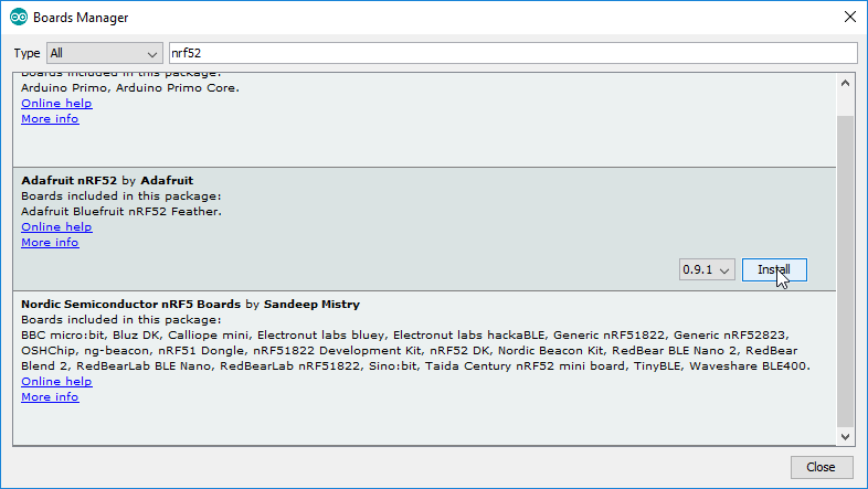
- Search for "nRF", and you should find the Adafruit nRF52 board package.
- Make sure the latest version is selected and click Install
https://github.com/adafruit/arduino-board-index/blob/gh-pages/package_adafruit_index.json but has been updated to https://adafruit.github.io/arduino-board-index/package_adafruit_index.json.
Installation may take a few minutes -- included in the install are all necessary source files for the Arduino core and nRF52 libraries, plus all of the compiler and software-upload tools you'll need to use the nRF52840 with Arduino.
Once the board definitions have been installed, you should see a new set of nRF52 boards under your Tools > Board menu. You won't, however, see an option for the SparkFun Pro nRF52840 Mini. For that, we need to manually add a new board.
Adding the SparkFun Pro nRF52840 Mini to the Board Menu
To add a "SparkFun Pro nRF52840 Mini" option to the nRF52 boards list, we need to make a couple small, manual modifications to the Arduino core you just installed.
Why the SparkFun Pro nRF52840 Mini board definitions?
The addition of these board modifications are not required for uploading code to your nRF52840 via Arduino. Most significantly, these board definitions help define pin-routing. They'll help to route the following serial buses and pins:
- Hardware Serial (
Serial1) to pins 17 (TX) and 15 (RX) to match the Arduino Pro Mini pinout - I2C to pins to 8 (SDA) and 11 (SCL). Important if you're using the qwiic connector.
- SPI to pins 31 (MISO), 3 (MOSI), 30 (SCK) – again matches the Arduino Pro Mini pinout.
- Built-in LED (
LED_BUILTIN) to pin 7
If you'd rather skip this step – even temporarily you can use Adafruit Bluefruit on nRF52840DK PCA10056 as your board selection.
To add SparkFun nRF52840 board support to the nRF52 Arduino core, one file (boards.txt) needs to be modified, and one new folder (variants/sparkfun_nrf52840_mini) needs to be copied in. You can grab the latest version of these files from our GitHub respository or by clicking the button below and unzipping the ZIP files contents:
To place the files, first navigate to your Adafruit nRF52 core installation. If you installed via the board manager it'll probably be in one of these folders:
- Windows:
%LOCALAPPDATA%\Arduino15\packages\adafruit\hardware\nrf52\<version> - OS X:
~/Library/Arduino15/packages/adafruit/hardware/nrf52/<version> - Linux:
~/.arduino15/packages/adafruit/hardware/nrf52/<version>
If you installed the core manually into your Arduino sketchbook, it'll be in "hardware/adafruit/nrf52".
Then open boards.txt. Scroll to the bottom and paste the below into the bottom of that file:
language:text
#**********************************************
# SparkFun Pro nRF52840 Mini
#**********************************************
sparkfunnrf52840mini.name=SparkFun Pro nRF52840 Mini

# DFU Mode with CDC only
sparkfunnrf52840mini.vid.0=0x1B4F
sparkfunnrf52840mini.pid.0=0x002A

# DFU Mode with CDC + MSC (UF2)
sparkfunnrf52840mini.vid.1=0x1B4F
sparkfunnrf52840mini.pid.1=0x0029

# Application with CDC + MSC
sparkfunnrf52840mini.vid.2=0x1B4F
sparkfunnrf52840mini.pid.2=0x8029

# CircuitPython
sparkfunnrf52840mini.vid.2=0x1B4F
sparkfunnrf52840mini.pid.2=0x802A

sparkfunnrf52840mini.bootloader.tool=bootburn

# Upload
sparkfunnrf52840mini.upload.tool=nrfutil
sparkfunnrf52840mini.upload.protocol=nrfutil
sparkfunnrf52840mini.upload.use_1200bps_touch=true
sparkfunnrf52840mini.upload.wait_for_upload_port=true
#sparkfunnrf52840mini.upload.native_usb=true

# Build
sparkfunnrf52840mini.build.mcu=cortex-m4
sparkfunnrf52840mini.build.f_cpu=64000000
sparkfunnrf52840mini.build.board=NRF52840_FEATHER
sparkfunnrf52840mini.build.core=nRF5
sparkfunnrf52840mini.build.variant=sparkfun_nrf52840_mini
sparkfunnrf52840mini.build.extra_flags=-DNRF52840_XXAA {build.flags.usb}
sparkfunnrf52840mini.build.vid=0x1B4F
sparkfunnrf52840mini.build.pid=0x5284
sparkfunnrf52840mini.build.usb_manufacturer="SparkFun"
sparkfunnrf52840mini.build.usb_product="nRF52840 Mini Breakout"

# SofDevice Menu
# Ram & ROM size varies depending on SoftDevice (check linker script)

sparkfunnrf52840mini.menu.softdevice.s140v6=s140 6.1.1 r0
sparkfunnrf52840mini.menu.softdevice.s140v6.build.sd_flags=-DS140
sparkfunnrf52840mini.menu.softdevice.s140v6.build.sd_name=s140
sparkfunnrf52840mini.menu.softdevice.s140v6.build.sd_version=6.1.1
sparkfunnrf52840mini.menu.softdevice.s140v6.build.sd_fwid=0x00B6
sparkfunnrf52840mini.menu.softdevice.s140v6.build.ldscript=nrf52840_s140_v6.ld
sparkfunnrf52840mini.menu.softdevice.s140v6.upload.maximum_size=815104
sparkfunnrf52840mini.menu.softdevice.s140v6.upload.maximum_data_size=248832

# Debug Menu
sparkfunnrf52840mini.menu.debug.l0=Level 0 (Release)
sparkfunnrf52840mini.menu.debug.l0.build.debug_flags=-DCFG_DEBUG=0 -Os
sparkfunnrf52840mini.menu.debug.l1=Level 1 (Error Message)
sparkfunnrf52840mini.menu.debug.l1.build.debug_flags=-DCFG_DEBUG=1 -Os
sparkfunnrf52840mini.menu.debug.l2=Level 2 (Full Debug)
sparkfunnrf52840mini.menu.debug.l2.build.debug_flags=-DCFG_DEBUG=2 -Os
sparkfunnrf52840mini.menu.debug.l3=Level 3 (Segger SystemView)
sparkfunnrf52840mini.menu.debug.l3.build.debug_flags=-DCFG_DEBUG=3 -Os
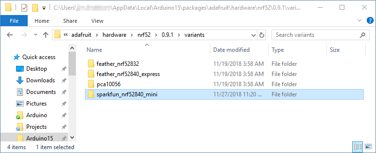
Then copy the contents of the "variants" folder in this directory into the "variants" folder of the original directory. Nothing should be overwritten, but a new "sparkfun_nrf52840_mini" directory should be added in.
After making these modifications, restart the Arduino IDE if it was open.
Installing adafruit-nrfutil
A program called adafruit-nrfutil is used to package and upload compiled code to the nRF52840 -- similar to what avrdude does for Arduino Uno's and other AVR boards.
If you're on a Windows or Mac machine, you can ignore this part. adafruit-nrfutil is automatically installed with the board definitions.
Linux users will need to manually install adafruit-nrfutil. adafruit-nrfutil is a Python-based program, to install it with PyPi type:
language:python
pip3 install adafruit-nrfutil --user
(You may need Python 3 installed if you don't already have it.)
Arduino Examples
Using the Arduino nRF52 cores, you can program digitalWrite I/O, analogRead ADC pins, Serial print to the Serial monitor, interact with hardware serial using Serial1, and even perform more complex I2C or SPI writes with the Wire and SPI libraries. But, if you've done any Arduino development before, those may not be all that exciting. Let's do some Bluetooth stuff!
The nRF52 Arduino core includes the Bluefruit nRF52 Libraries which can be used to turn your nRF52840 into a BLE peripheral and/or central device. Browse the exhaustive list of examples by navigating to File > Examples > Adafruit Bluefruit nRF52 Libraries. One suggestion, if you want to start simple, is the peripheral/blinky_ota example.
Blinky Button BLE Example Code
As if you don't already have enough examples, we wanted to provide a simple example that demonstrates how to control and interact with the nRF52840's hardware components over a BLE connection. This example allows you to toggle the LED and read the pin-13 button status using a BLE app on your mobile phone.
To get the example, copy and paste the below into a new Arduino sketch in your IDE (or get the latest version in our GitHub repo):
language:c
/* BLE Example for SparkFun Pro nRF52840 Mini
 *
 *  This example demonstrates how to use the Bluefruit
 *  library to both send and receive data to the
 *  nRF52840 via BLE.
 *
 *  Using a BLE development app like Nordic's nRF Connect
 *  https://www.nordicsemi.com/eng/Products/Nordic-mobile-Apps/nRF-Connect-for-Mobile
 *  The BLE UART service can be written to to turn the
 *  on-board LED on/off, or read from to monitor the
 *  status of the button.
 *
 *  See the tutorial for more information:
 *  https://learn.sparkfun.com/tutorials/nrf52840-development-with-arduino-and-circuitpython#arduino-examples
*/
#include <bluefruit.h>

BLEUart bleuart; // uart over ble

// Define hardware: LED and Button pins and states
const int LED_PIN = 7;
#define LED_OFF LOW
#define LED_ON HIGH

const int BUTTON_PIN = 13;
#define BUTTON_ACTIVE LOW
int lastButtonState = -1;

void setup() {
  // Initialize hardware:
  Serial.begin(9600); // Serial is the USB serial port
  pinMode(LED_PIN, OUTPUT); // Turn on-board blue LED off
  digitalWrite(LED_PIN, LED_OFF);
  pinMode(BUTTON_PIN, INPUT);

  // Uncomment the code below to disable sharing
  // the connection LED on pin 7.
  //Bluefruit.autoConnLed(false);

  // Initialize Bluetooth:
  Bluefruit.begin();
  // Set max power. Accepted values are: -40, -30, -20, -16, -12, -8, -4, 0, 4
  Bluefruit.setTxPower(4);
  Bluefruit.setName("SparkFun_nRF52840");
  bleuart.begin();

  // Start advertising device and bleuart services
  Bluefruit.Advertising.addFlags(BLE_GAP_ADV_FLAGS_LE_ONLY_GENERAL_DISC_MODE);
  Bluefruit.Advertising.addTxPower();
  Bluefruit.Advertising.addService(bleuart);
  Bluefruit.ScanResponse.addName();

  Bluefruit.Advertising.restartOnDisconnect(true);
  // Set advertising interval (in unit of 0.625ms):
  Bluefruit.Advertising.setInterval(32, 244);
  // number of seconds in fast mode:
  Bluefruit.Advertising.setFastTimeout(30);
  Bluefruit.Advertising.start(0);
}

void loop() {
  // If data has come in via BLE:
  if (bleuart.available()) {
    uint8_t c;
    // use bleuart.read() to read a character sent over BLE
    c = (uint8_t) bleuart.read();
    // Print out the character for debug purposes:
    Serial.write(c);

    // If the character is one of our expected values,
    // do something:
    switch (c) {
      // 0 number or character, turn the LED off:
      case 0:
      case '0':
        digitalWrite(LED_PIN, LED_OFF);
        break;
      // 1 number or character, turn the LED on:
      case 1:
      case '1':
        digitalWrite(LED_PIN, LED_ON);
        break;
      default:
        break;
    }
  }

  // If our button state has changed:
  int buttonState = digitalRead(BUTTON_PIN);
  if (buttonState != lastButtonState) {
    lastButtonState = buttonState;
    // Write the new button state to the bleuart TX char
    bleuart.write(!buttonState);
  }
}
Before uploading, make sure you've selected SparkFun Pro nRF52840 as your board (or "Adafruit Bluefruit on nRF52840DK PCA10056" if you didn't install the SparkFun board definition.
Using nRF Connect to Control the Board
To test this example sketch, you'll need another device -- either computer or smartphone -- connected to your nRF52840. Nordic provides a free, handy test tool, nRF Connect for Mobile, that's available for both Android or iOS. We'll demonstrate how to control your nRF52840's LED and monitor the button using this sketch. So go download the app!
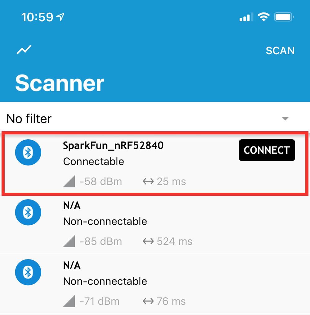
Once downloaded, open the app and begin searching for nearby Bluetooth devices. Among those with a strong signal strength, you should see SparkFun_nRF52840. Click the "CONNECT" button next to that.
Once connected, click on the Nordic UART Service, where you'll be presented with a pair of characteristics: TX and RX. Contrary to what you might expect, the "TX" characteristic is used to read the button status, and "RX" writes to the LED.
To read the button state, click the triple-down-arrow icon to the right of the "TX" characteristic. This will subscribe to notifications. If you press and release the button, you should see the "Value" change from 0x00 to 0x01 and back.
To write to the LED, click the up-arrow on the "RX" characteristic. Select "Text" as your format. Then write either "0" or "1" into the text box and press "SEND". A "0" will turn the LED off and a "1" will turn it on.
Check out the code comments to see how the bleuart service is used to control these two characteristics. And check out the rest of the examples in the Bluefruit for nRF52 library! There's some great stuff in there!
CircuitPython Installation
Are you looking for an escape from C/C++ or Arduino? Want to turn your nRF52840 into a Python-interpreting wonder? Check out the nRF port of CircuitPython!
Alpha Development
Please note that development on the CircuitPython port for the nRF52840 is still in very early stages of development. You're part of something exciting, but things might not always work as expected.
If you ever find your nRF52840 in an unknown state, you can always factory reset it -- essentially erasing any application and preserving the bootloader. For instructions on factory resetting, check out the Pro nRF52840 Mini Hookup Guide.
Flashing CircuitPython
The nRF52840's UF2 bootloader, which presents a drag-and-drop, USB mass-storage-device-based programming interface, can be used to flash CircuitPython onto your board.
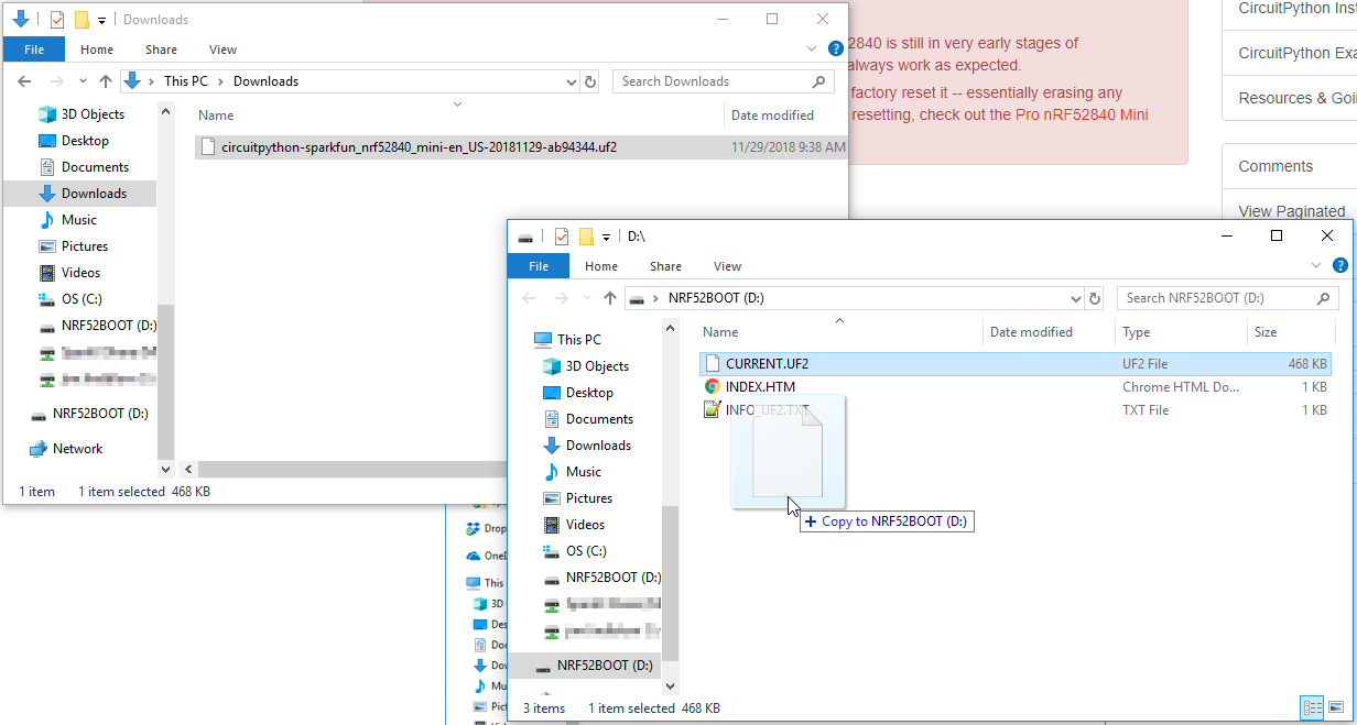
To begin, download our latest release of the CircuitPython firmware. It's packaged as a .UF2 file.
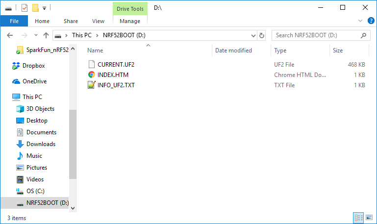
Next put your nRF52840 Mini into bootload mode. Either double-tap the reset button, or hold pin-13 down while tapping the reset button. Your computer should find an "NRF52BOOT" device that looks like a removable USB drive.
Now simply drag the UF2 file onto NRF52BOOT. After the file copies over, you may get a warning indicating that the file is too large -- this should be safe to ignore (hit "Cancel").
After the firmware is programmed, a new drive should pop up on your computer: CIRCUITPY. Just as you programmed the firmware on, you'll drag-and-drop Python files into this folder to run new applications.
CircuitPython Examples
New platform? New programming language? Time to blink some LEDs! Copy the code below to start blinking the blue LED on pin 7:
language:python
import time
import board
from digitalio import DigitalInOut, Direction, Pull

led = DigitalInOut(board.P0_07)
led.direction = Direction.OUTPUT

while True:
    led.value = False
    time.sleep(0.5)
    led.value = True
    time.sleep(0.5)
Then create a new file named code.py and paste the above code into it. (Or you can download blinky.py and rename it "code.py" if you prefer.) Note that CircuitPython is expecting a Python file explicitly named "code.py" for its Python application. If your file is named something else, it won't run.
After the file loads, you should be presented with that comforting blinking light.
Want to change up the time delay? Feel free to edit the "code.py" script directly on the CIRCUITPY drive. After you save, it should reload the script and run it anew.
Here's another example pulling in button-support:
language:python
import time
import board
from digitalio import DigitalInOut, Direction, Pull

led = DigitalInOut(board.P0_07)
led.direction = Direction.OUTPUT

button = DigitalInOut(board.P0_13)
button.direction = Direction.INPUT
button.pull = Pull.UP

while True:
    if not button.value:
        print("Button pressed!")
        led.value = True
    else:
        led.value = False

    time.sleep(0.01)
After saving that, you should be able to toggle the LED by tapping the pin 13 button.
Troubleshooting
As noted, CircuitPython support for the nRF52840 is still in a very early release stage. Here are a few tips for escaping some of the more common pitfalls.
Debugging the Python
If you're a seasoned Python developer, or really done any Python work at all, you know how critical the terminal can be to tracing-back errors. Luckily a debugging port is built in to CircuitPython too!
CircuitPython enumerates as a serial port on your computer -- something in the form of COM## for Windows or /dev/tty.usbmodem###### on Mac. Find the port, then open up your favorite serial terminal setting the baud rate to 115200.
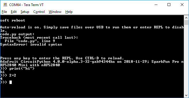
The terminal also features a REPL (read-eval-print loop) interface, which you can access by pressing enter in the terminal. That comes in especially handy for the next issue...
File Corruption
File corruption issues are not uncommon in CircuitPython. Maybe Windows doesn't like the way you ejected the drive. If you're having issues opening or even deleting "code.py", try this:
Follow the instructions above to open your CircuitPython terminal. Then press Enter to enter REPL mode.
Then type these two instructions:
language:python
>>> import storage
>>> storage.erase_filesystem()
This will delete all files contained within CircuitPython's filesystem. You should now be able to drag a new code.py on and keep going.
For more troubleshooting tips, check out the CircuitPython Troubleshooting Guide.
Resources and Going Further
Hopefully that gets you on the right track to developing a truly awe-inspring Arduino or Python-based nRF52840 project.
If you need more guidance or resources, here are a few resources to check out:
- Arduino
- Arduino Core GitHub Repository -- Home base for all of the core source, examples, and tools.
- SparkFun Board Definitions - SparkFun board definitions for the SparkFun Pro nRF52840 Mini.
- adafruit-nrfutil GitHub Repository -- adafruit-nrfutil is the tool required to upload Arduino sketches to your nRF52840 via the bootloader. This is where the source code is stored and developed-upon.
- CircuitPython
- CircuitPython API Reference -- Exhaustive documentation hub for all CircuitPython API.
- CircuitPython GitHub Repository -- Home base for all CircuitPython-related source and tools. Make sure to check out the ports/nrf directory for info specific to the nRF52840.
- Building CircuitPython Tutorial -- If you want to build a CircuitPython variant of your own, give this a read.
If you're looking to take your development to the next level, check out our nRF52840 nRF5 SDK Development Guide. This advanced tutorial documents how to use the nRF5 SDK to build your nRF52840 application in C.