SparkFun gator:bit v2 Hookup Guide
 LightningHawk,
  Englandsaurus
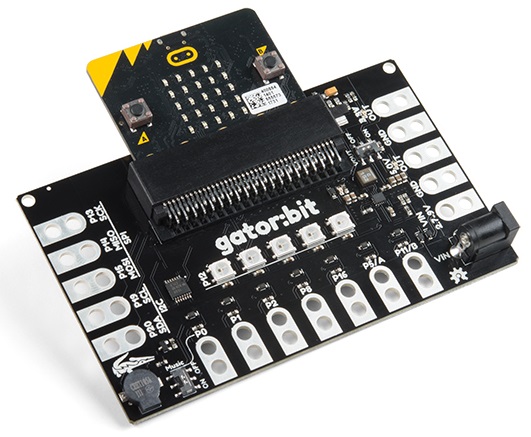
Hardware Overview
Features:
|
|
Powering Your gator:bit
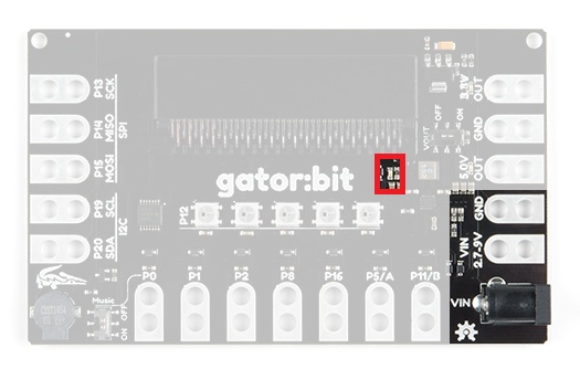
There are 3 ways of powering your gator:bit v2, either from the barrel jack, the alligator clippable pads labeled VIN, or through the micro:bit itself. On the gator:bit, any input voltage between 2.7V and 9V will be regulated to 3.3V to power the micro:bit, the speaker, and for use by any of the alligator clippable pins. 5V is also regulated or boosted from the input voltage to power the LEDs and any off-board hardware you would like to use like servo motors. When the gator:bit is powered, the power indication LED, highlighted in red below, will turn on.
Whether you are providing power from either the barrel jack or from a clipped source, the gator:bit can be used with a USB on the micro:bit. The power circuitry for the gator:bit is arranged so that the board uses the largest power source.
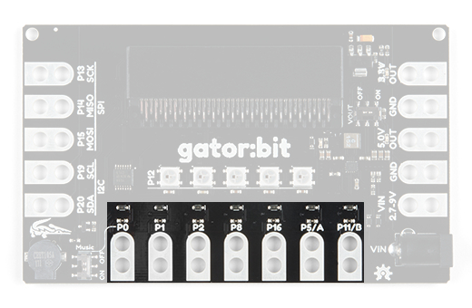
Input Pins
I/O Protected Pins
The point of gator:bit (v2) is to give you access to as much GPIO as possible from the micro:bit, safely. Not only are pins 0, 1, 2, 8, 16, 5 (Button A), and 11 (Button B) broken out, but they are also protected against overvoltage and overcurrent/short circuit. Pins 0, 1, and 2 are ADC pins; while, pins 8, 16, 5, and 11 are digital pins capable of read and write.
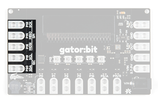
I2C and SPI Serial
The gator:bit also provides access to pins 13, 14, 15, 19 & 20. These are digital pins that can be used to read and write digital signals. Pins 13, 14, & 15 are also SPI communication pins giving you the ability to use SparkFun's SPI sensors with the gator:bit. Pins 19 & 20 are I2C communication pins which extend the use of the micro:bit to include all of SparkFun's I2C sensors.
Outputs
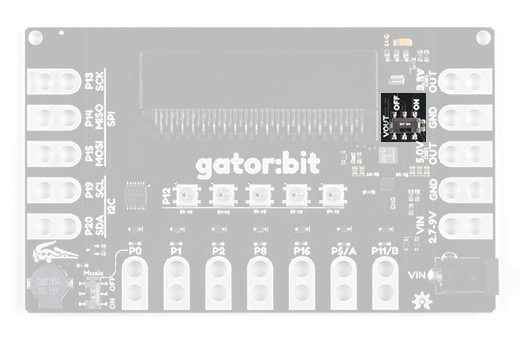
Voltage Output
The gator:bit (v2) gives you access to more micro:bit pins and it also gives you access to 3.3V and 5V. Your servo action is about to get a little cleaner and you'll be able to easily power peripheral hardware.
In order to use the voltage out tabs, the VOUT switch needs to be switched on. Having the option to turn it off is great when when you don't need it.
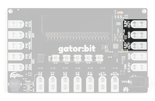
On the right side of the board there are two "OUT" pins. One for 5V and one for 3.3V. You will know when the output voltage is available because two red LEDs will turn on right above the pad. You can use either of the two ground pads since all ground is connected.
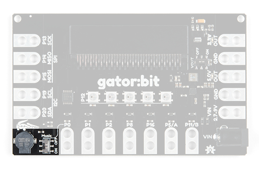
Now let's look at the fun kind of output, light and sound! On the bottom left is a buzzer. We chose a small speaker on purpose. You'll be able to explore creating digital music and then listen to it right on the gator:bit. You can easily attach a larger speaker when you are ready to show off your work.
Piezo Speaker
You'll notice another switch here. The speaker is attached to pin 0, so if you want to play music the music switch needs to be on and you won't be able to use pin 0. Conversely, if you want to use pin 0, the music switch needs to be switched off.
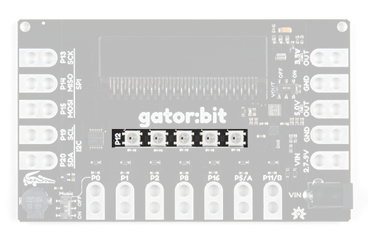
Addressable LEDs
LEDs! Addressable LEDs! Connected to pin 12 are 5 addressable LEDs with the first LED on the left. The Neopixel MakeCode extension is an excellent way to control these. We have a few examples using the extension coming up.