SparkFun BME280 Breakout Hookup Guide
Contributors:
 MTaylor
MTaylor 
Hardware Overview
The Front Side
The BME280 Breakout board has 10 pins, but no more than 6 are used at a single time.
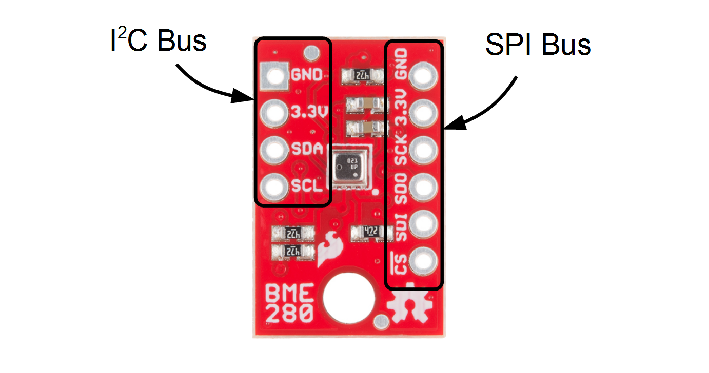
Use one header for I2C connections, or the other for SPI connections -- no need to use both!
The left side of the board are power, ground, and I2C pins.
| Pin Label | Pin Function | Notes |
|---|---|---|
| GND | Ground | 0V voltage supply. |
| 3.3v | Power Supply | Supply voltage to the chip. Should be regulated between 1.8V and 3.6V. |
| SDA | Data | I2C: Serial data (bi-directional) |
| SCL | Serial Clock | I2C serial clock. |
The remaining pins are broken out on the other side. These pins break out SPI functionality and have another power and ground.
| Pin Label | Pin Function | Notes |
|---|---|---|
| GND | Ground | 0V voltage supply. |
| 3.3v | Power Supply | Supply voltage to the chip. Should be regulated between 1.8V and 3.6V. |
| SCK | Clock | Clock line, 3.6V max |
| SDO | Data out | Data comming out of the BME280 (MISO) |
| SDI | Data in | Data going into the BME280, 3.6V max (MOSI) |
| !CS | Chip Select (Slave Select) | Active low chip select, 3.6V max |
The Back Side
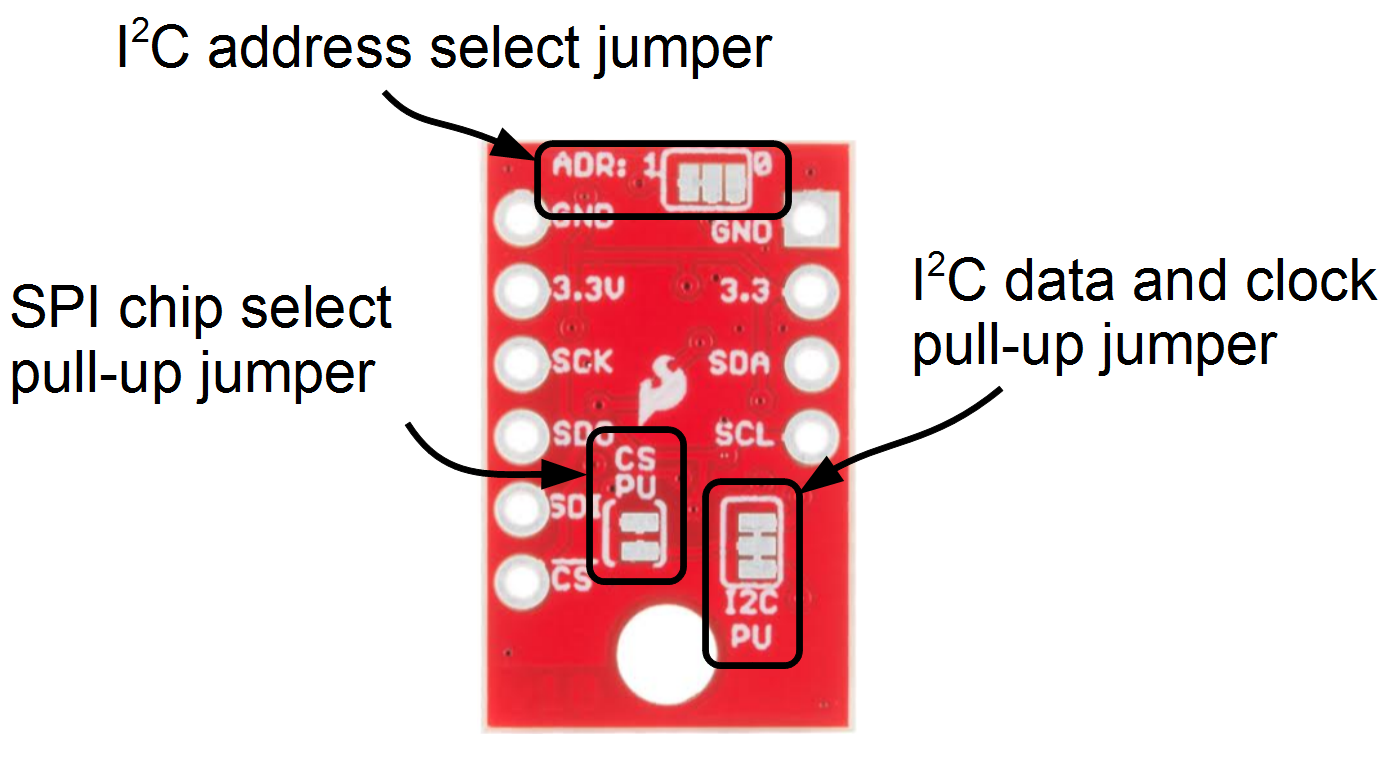
On the other side of the board you'll find all the configuration jumpers. Pull-ups can be left connected even when using SPI mode, so you'll probably never have to touch these. If you do, here's what they're for.
| Jumper Label | Jumper Function | Notes |
|---|---|---|
| ADR: | I2C Address | Select between addresses 0x77 (default, '1' side) and 0x76 by slicing the trace and bridging the '0' side. Controls the least significant bit. |
| CS PU | SPI chip select pull-up | Connects a 4.7k resistor to the CS line to make sure it is idle high. Can be disconnected by slicing between the jumper pads. |
| I2C | I2C pull-ups | Connects the I2C pull-up resistors to 3.3V. Cut the trace to disconnect them if necessary. |