SparkFun Blocks for Intel® Edison - PWM
Contributors:
 SFUptownMaker,
  CaseyTheRobot,
  HelloTechie
SFUptownMaker, CaseyTheRobot, HelloTechie 
Board Overview
The "top" side of the board is the most interesting, so we'll look at that first.

- PWM outputs - Each PWM channel has a three-pin, 0.1" spaced header footprint. The output order is appropriate for most servo motors. All you need to do is add male header pins, and you can connect servos directly to the block. The VIN pin is, by default, floating. Before you can drive a servo, you'll need to provide power to that rail.
- Auxiliary Power Input - These pads are provided to allow you to connect an external power supply to the PWM channels. This allows you to use a higher voltage, higher current supply (for instance, a 7.2V 2S LiPo cell) to power the devices connected to the PWM outputs without risking damage to the Edison.
- VSYS->VIN jumper - If you don't need the extra oomph of an external power supply (because you're driving small LEDs or a small servo, perhaps), you can bridge this jumper with a solder blob to draw power from the Edison VSYS rail. When running from USB, you can expect that rail to be approximately 4.0V.
- Address jumpers - These jumpers allow you to set the address the PCA9685 PWM chip on this board will use. Each jumper corresponds to a single address bit; closing a jumper makes that bit a '1'. The default address is 0x40. Thus, closing A0 would make the address 0x41, A1 makes it 0x42, A0 and A1 make it 0x43, and so on.
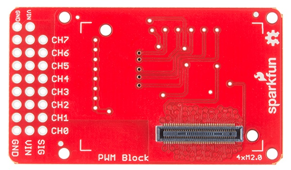
The "back" of the board is far more boring, with no jumpers or components to mention. This is the side that the Edison module will mate with, so you will be able to change jumpers without detaching the Edison.