SparkFun Blocks for Intel® Edison - I2C Breakout Block
Introduction and Overview
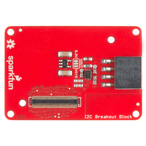
The I2C Breakout Block is a simple way to integrate an I2C device with an Intel Edison stack. The I2C block has the ability to supply 3.3V or VSYS power to external I2C sensors. This opens up the Edison to the great variety of I2C devices we, and others, have to offer.
Suggested Reading
If you are unfamiliar with Blocks, take a look at the General Guide to Sparkfun Blocks for Intel Edison.
Other tutorials that may help you on your Edison adventure include:
Board Overview
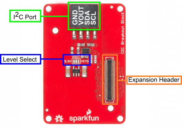
I2C Port - Standard I2C port broken out. VOUT provides power based on Level Select position.
Level Select - Provides level selection between 3.3V and VSYS levels on VOUT. Default 3.3V
Expansion Header - The 70-pin Expansion header breaks out the functionality of the Intel Edison. This header also passes signals and power throughout the stack. These function much like an Arduino Shield.
Using the I2C Breakout Block
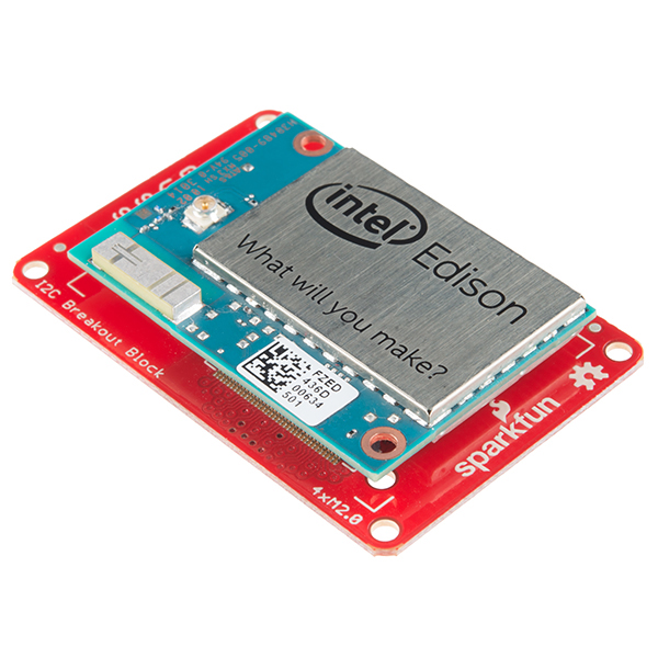
To use the I2C Breakout Block, attach an Intel Edison to the back of the board or add it to your current stack. Blocks can be stacked without hardware, but it leaves the expansion connectors unprotected from mechanical stress.
We have a nice Hardware Pack available that gives enough hardware to secure three blocks and an Edison.
NOTE: The I2C Breakout Block does not have console access or a power supply. It is recommended to use a console communication block in conjunction with this block like ones found in the General Guide to Sparkfun Blocks for Intel Edison.
Example
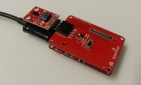
In our example, we will show how to connect and scan for the SparkFun RGB and Gesture Sensor. Solder a 4-pin section of our Right Angle Break Away Male Headers to the breakout board. Plug the board into the I2C Brekaout Block, and you're done with the hardware connection.
To find the I2C device in the console, type the following command. Note the I2C bus we will use is bus 1.
i2cdetect -y -r 1
We see that the device appears on address 0x39 as expected.
     0  1  2  3  4  5  6  7  8  9  a  b  c  d  e  f
00:          -- -- -- -- -- -- -- -- -- -- -- -- --
10: -- -- -- -- -- -- -- -- -- -- -- -- -- -- -- --
20: -- -- -- -- -- -- -- -- -- -- -- -- -- -- -- --
30: -- -- -- -- -- -- -- -- -- 39 -- -- -- -- -- --
40: -- -- -- -- -- -- -- -- -- -- -- -- -- -- -- --
50: -- -- -- -- -- -- -- -- -- -- -- -- -- -- -- --
60: -- -- -- -- -- -- -- -- -- -- -- -- -- -- -- --
70: -- -- -- -- -- -- -- --
To use the SparkFun RGB and Gesture Sensor in your project, you can modify the code from the RGB and Gesture Sensor Hookup Guide to run on your Edison. Using the Arduino IDE for Edison, the demo should work out of the box!
Using 5V Devices
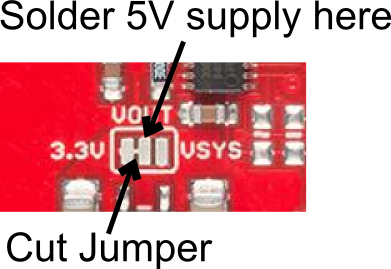
There is a way to modify the I2C block to accept 5V logic. Cut the voltage select jumper, but do not re-connect to either VSYS or 3.3V. You will now need to supply your own 5V voltage (for your sensors) externally. You can solder a 5V supply to the center pad OR use the VOUT pin on the connector. Supplying 5V through the VOUT trace will allow you to plug sensors in without modification.
Resources and Going Further
Now that you have had a brief overview of the I2C Breakout Block, take a look at some of these other tutorials. These tutorials cover programming, Block stacking, and interfacing with the Intel® Edison ecosystems.
Edison General Topics:
- General Guide to Sparkfun Blocks for Intel Edison
- Edison Getting Started Guide - Programming with Arduino
- Loading Debian (Ubilinix) on the Edison
Block Specific Topics:
Check out these other Edison related tutorials from SparkFun:
