SparkFun Blocks for Intel® Edison - Arduino Block
 jimblom
Board Overview
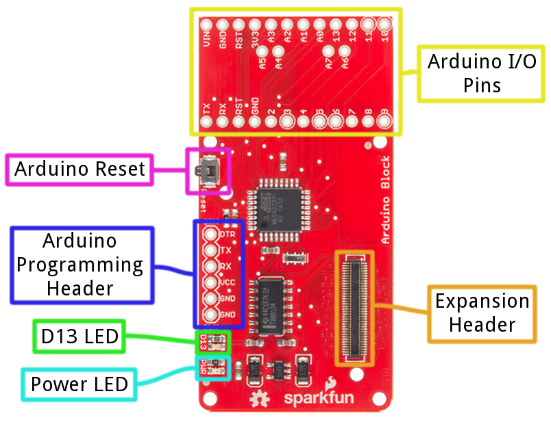
- Expansion Header -- The 70-pin Expansion header breaks out the functionality of the Intel Edison. This header also passes signals and power throughout the stack. These function much like an Arduino Shield.
- Arduino I/O Pins -- All of the Arduino's I/O pins are broken out to a pair of headers (plus a couple in between). This header footprint exactly matches that of the Arduino Pro Mini -- if you have any Mini shields they should mate exactly to this header.
- Arduino Programming Header -- The standard 6-pin FTDI header is used to program the Arduino's serial bootloader. Plug a 3.3V FTDI Basic in to program your Arduino.
- D13 LED -- Every good Arduino needs an LED! This small, green LED is tied to the Arduino's pin 13. Great for blinking "Hello, world" or debugging.
- Power LED -- The Arduino block has an on-board 3.3V regulator, and this LED is tied to the output of that regulator.
- Arduino Reset Button -- This reset button is tied to the Arduino's reset line. It will only reset the Arduino; it has no effect on the Edison.
Schematic Overview
The Arduino block pairs the ATmega328 to your Edison via one of two UARTs. The board defaults to connecting the Arduino to Edison via UART1. Jumpers (see more below) allow you to select UART2, if your application requires. Take care using UART2, though, it's default utility is for console access to the Edison.
The Arduino Block has an on-board 3.3V voltage regulator, which takes its input from the Edison's VSYS bus. Since the Arduino is running at 3.3V, its clock speed is limited to 8MHz.
If you want to take a closer look at the schematic, download the PDF here.
Jumpers
On the back-side of the Arduino block, there are a handful of jumpers, which lend extra utility to the board.
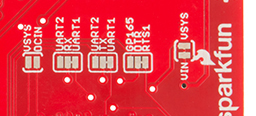
Three two-way jumpers -- for RX, TX, and DTR -- allow you to select between UART1 (default) and UART2. To switch these jumpers, grab a hobby knife, cut the default traces, and drop a solder blob between the middle pad and outer pad of your choice.
The jumper labeled VIN/VSYS allows you to remove the VSYS line from powering the Arduino block. This is handy if you need to isolate the Arduino block's power source from the Edison. In this case, you'll need to supply power (3.3-12V) externally via the "VIN" pin.