Simon Says Experiments
 QCPete,
  bboyho
Hardware Assembly
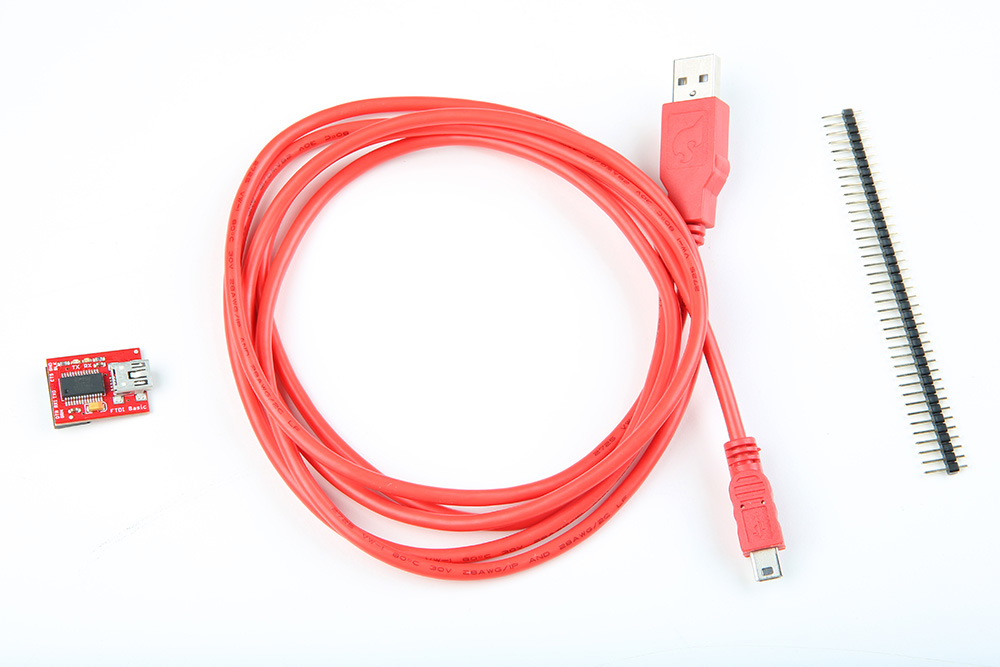
To upload new code to the board, we need a mini-B USB Cable, FTDI basic Breakout, and a 1x6 row from a row of straight male headers.
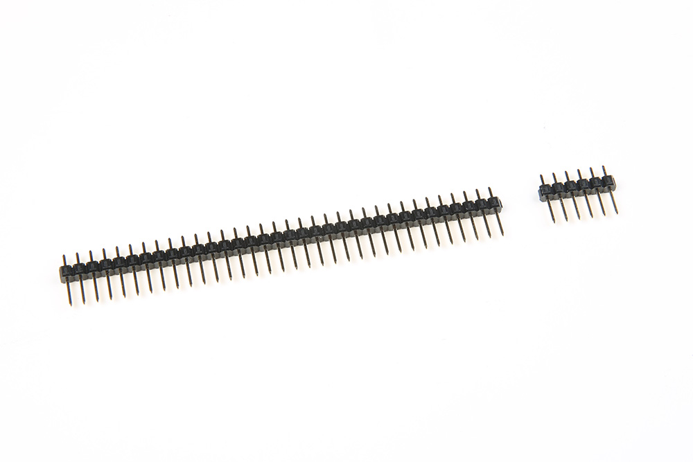
If you bought a 40-pin strip of breakaway male headers from the website, you will have to break off a 6-pin section from the larger strip. You can cut these using some pliers, or snap them using your hands by bending the strip at the desired break-point.
These 3 items will be the link between your Simon Says board and your computer. First, plug in the 6-pin male header into your FTDI basic board. Make sure to put the longer end of the headers into the FTDI like so:
|
|

|
Next, plug in the USB cable into your computer. Then plug the other end into your FTDI basic board. You should notice that the RX and TX leds on the FTDI blink a few times. This indicates that your FTDI is communicating with your computer.
|
|
|
Now you are ready to link your computer to your Simon Says board. First you must find the programming port on your Simon Says board. You will find it near one of the edges of the Simon Says board. It looks like 6x holes with nothing soldered into them. Below shows images of the FTDI header for the PTH and SMD versions.

|

|
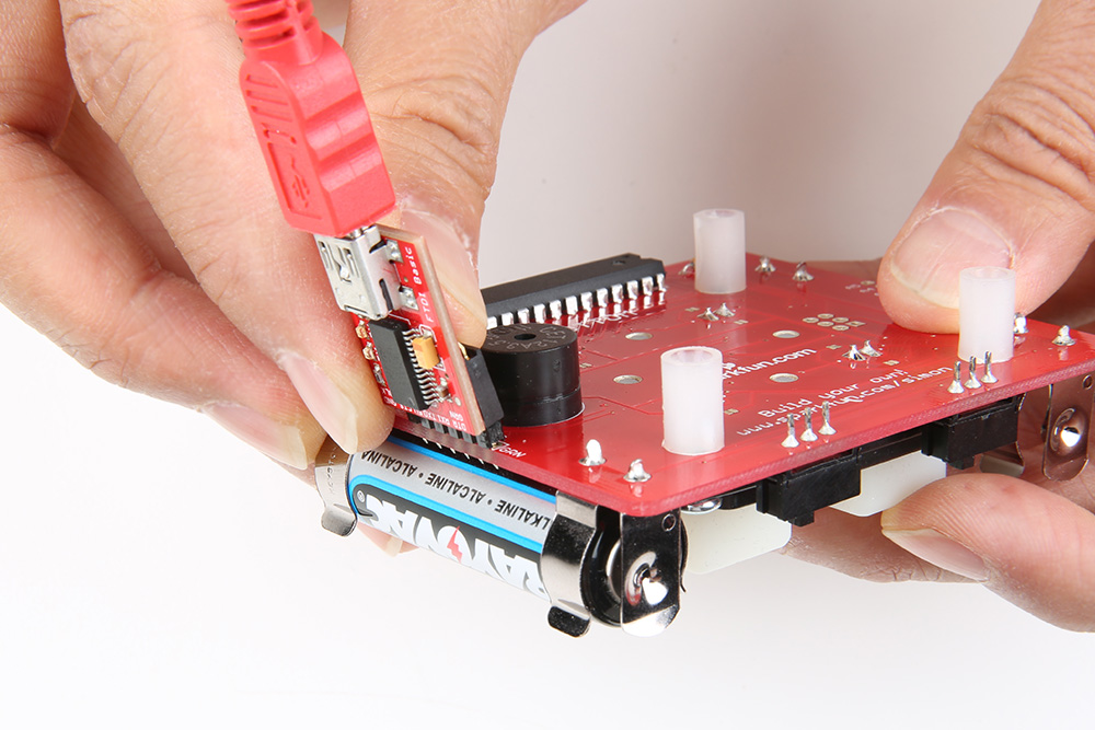
To reprogram your board, you are going to push the 6-pin header (that is already plugged into your FTDI board) into this port. You will have to hold it at an angle to cause a temporary connection. You will also need to make sure you align it properly. If you flip your board upside down, then you should see that the holes are labeled with some white ink. Look for the two pins labeled, “GRN” and “BLK”. These indicate the proper alignment of your FTDI board so that it is GRN to GRN and BLK to BLK.