Simon Says Experiments
 QCPete,
  bboyho
 Example: Disco Mode!
This part of this tutorial requires a couple more pieces of hardware and a soldering iron.
Using these parts and a little bit of code, we can detect light. This will be useful in detecting whether the lights are ON or OFF in a room. In the Disco Mode example code, we will have the Simon Says board only go into Disco Mode when the lights are off – when it's time to get your boogie on!
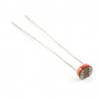
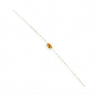
First off, let's take a look at the two components. Do you recognize that resistor from building your Simon Says? It's the exact same component you soldered into place when you built up your kit!!
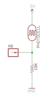
Next, let's take a look at the schematic for the light sensing circuit! Don't be scared – it's actually quite simple! A schematic is a drawing that represents physical things. It shows us how we are going to connect the two components to the Simon Says board. The green lines represent “nets” or connections. The other symbols represent actual things (like the photocell and resistor). The last three things in the schematic represent pin-outs on the Simon Says board. (GND, A0, and 5V).
Let's find these 3 holes on the Simon Says board. They are located on the bottom side underneath one of the batteries.

Next, let's twist the Photocell and resistor together in a way that will work with the schematic. Notice in the schematic how A0 is actually connected to both the photocell and the resistor. In order to solder this connection, it is helpful to twist one leg of the photocell and one leg of the resistor together. Make sure that there is enough room to insert the twisted pins into analog pin A0 before soldering.
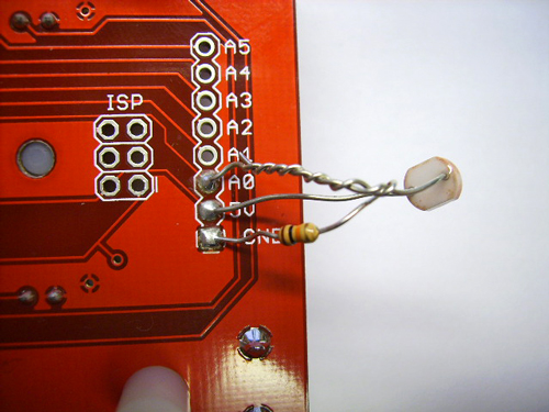
Now we have essentially 3 legs that will solder into 3 pinouts on the Simon Says. Before we begin to solder, please check out this picture below that shows how the legs should connect to the Simon Says.
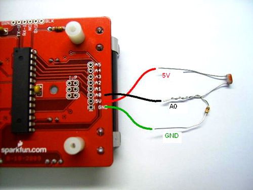
Notice how 5V and A0 are going to have to overlap. Be sure to remove your batteries before you start soldering. When you are finished soldering them into place, it should look something like this:
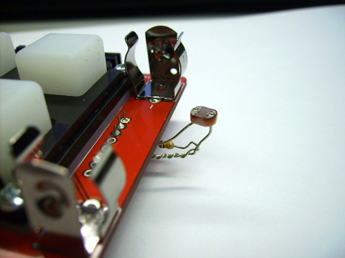
You can bend it around the edge so that the photocell is facing up and will do a better job of detecting the light. Like so:
You are almost ready to upload the Disco Mode Code! First, put your batteries back in and turn your board ON. Then open up the Arduino Software and open "SIMON_DISCO_MODE.ino". While holding your FTDI in place, click the upload button.
After the code is on there, try killing the lights and see if disco mode starts up!! If so, congratulations! You have just successfully completed your first embedded electronics project!