Si7021 Humidity and Temperature Sensor Hookup Guide
 Joel_E_B
Hooking It Up
Wiring up the Si7021 is very easy! We recommend soldering four male headers to the breakout board. You can also solder wires if your application needs.
Power
This board runs at 3.3V. Be sure to power the board from the 3.3V pin! Because I2C is an open drain signal, there's no need to worry about level shifting the signal; the 3.3V signal will be adequate to communicate with the Arduino and the signal will never reach a dangerous level for the pins on the Si7021.
Connections: Breakout to Arduino
Method 1
There are two ways to connect an Si7021 to an Arduino. The first is using pins A4 and A5 on classic Arduino boards. This breakout was designed using our standard I2C pinout, allowing the sensor to be connected directly to an Arduino without using a breadboard or wires.
- GND → A2
- VCC → A3
- SDA → A4
- SCL → A5
This would look like the following:
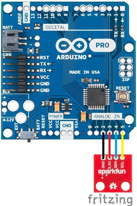
Also, if using this wiring scheme, be sure to assign pins A2 and A3 as GND and VCC, respectively, in your code.
If you need to use this device with a 5V microcontoller, you will need to use a Logic Level Converter.
Method 2
This method is for those with newer model Arduino boards that have the SDA and SCL lines broken out. We'll be hooking up VCC and GND to the normal power pins and two data lines for I2C communication. Connect the SDA and SCL lines directly to the SDA and SCL lines broken out on the Arduino headers.
- VCC → 3.3V
- GND → GND
- SDA → SDA
- SCL → SCL
This would look something like the following:
