RN-52 Bluetooth Hookup Guide
 Joel_E_B
Overview
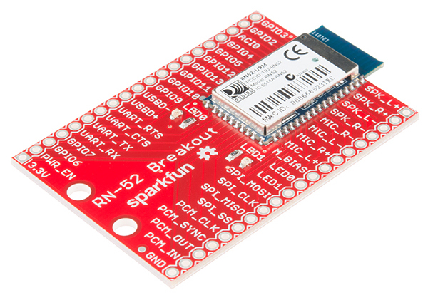
The RN-52 Audio Bluetooth Breakout is a sleek Bluetooth audio module from Roving Networks broken out on an easy to use PCB. It allows you to send stereo audio over a wireless Bluetooth connection. The module has an embedded DSP that handles the audio stream entering and exiting the module, converting the digital wireless signals into audio and vice versa. The module is easy to configure with both ASCII commands and GPIO. It can function as a stand alone module, or it can be incorporated with a microprocessor to create the ultimate wireless audio experience.
Covered in this Tutorial
In this tutorial, we will go over some of the module's features. We'll show you how to configure the module to suit your projects needs, how to hook it up, and go over a simple example project using the RN-52.
Suggested Reading
The RN-52 Module
Before we get in to the breakout board, let's discuss the module and its features.
As with any product, it is wise to read the datasheet before embedding this device into a project.
Bluetooth Version
The RN-52 is a Bluetooth v3.0 module. It is compatible with all Bluetooth v3.0 devices and also backwards compatible with all Bluetooth v2.1 + EDR, 1.2, and 1.1 devices.
Bluetooth Profiles
Here is a list of all the profiles that the RN-52 supports.
- SPP - Serial Port Profile allows you to configure the device over a UART serial connection. This can also be used to send commands to the module from a microcontroller.
- HFP/HSP - Support of both Hands-Free Profile and Headset Profile mean the module can act as a headset device. This allows the it to send audio back and forth, just like a Bluetooth headset. You can send audio input through a microphone and receive audio output through a speaker or headphones.
- A2DP - Advanced Audio Distribution Profile sends audio in one direction, but the quality of that audio is better than the quality of HFP and HSP.
- AVRCP - A/V Remote Control Profile allows you to control certain features of your audio through the module. Tasks such as Play/Pause, Volume Up, and Volume Down can be controlled by inputs on the module.
- iAP - This is the iPod Accessory Protocol, and it allows you to connect the module to any Apple devices such as iPhones, iPods, and Mac laptops and computers.
*Note: Multiple profiles can be implemented at once. The default settings are set to have all profiles discoverable.
Range
The RN-52 is a Class 2 Bluetooth device, meaning that the range of the on board antenna is about 10m. Thus, you should be able to stream audio to the module from about 32 ft in open air. If you are streaming through walls or windows, that range will diminish.
Wireless Audio
The RN-52 is different than other Bluetooth modules in that it can stream audio. It does this via an on-board Digital Signal Processing (DSP) chip. When streaming audio to the RN-52, the DSP converts the radio waves sent from the transmitter device (phone, computer, etc.) into electrical signals that can then be sent to the amplifier and then to your audio output (speakers/headphones). When streaming audio from the module, it converts the electrical signals from the audio input device (mic/line-in) to radio waves for the receiver device (stereo, computer, phone).
Many people ask why it isn't possible to send audio over just any old Bluetooth connection. The lack of an on-board DSP is the main reason most "regular" modules cannot support audio streaming.
Communication
Aside from a wireless Bluetooth connection, the RN-52 has four paths on which it can communicate to outside devices: UART, USB, SPI, and PCM. We'll discuss these in more depth in the next section.
The RN-52 Breakout
There is a lot going on with the RN-52 breakout board. Let's break it up into sections to find out what pins are needed for what purposes.
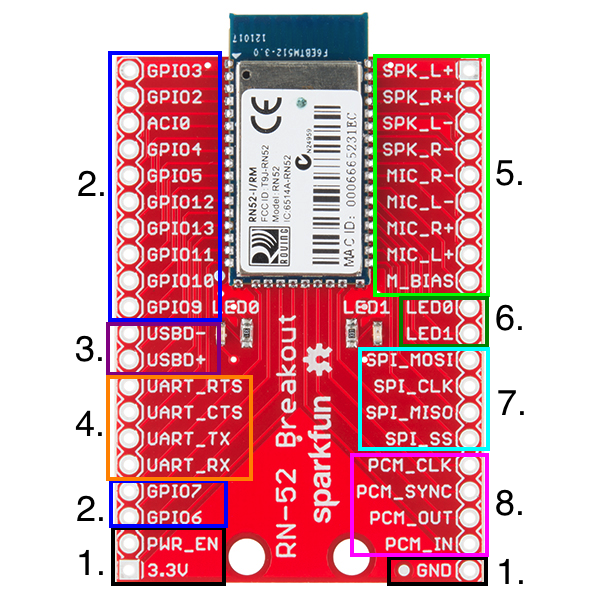
1. Power
Powering the RN-52 is very simple. There are three pins necessary to power the board, 3.3V, GND, and power enable (PWR_EN). The supply voltage should be in the 3.0 ~ 3.6V range.
2. GPIO Pins
The RN-52 has eleven general purpose input/output pins (GPIO). Many of these pins are reserved for special functions when the module is booted up and when the module is running. These pins also act as input pins for specific functions during audio playback. These can be configured to control media programs such as iTunes or Windows Media Player (eg. Play, Pause, Next Song, etc.).
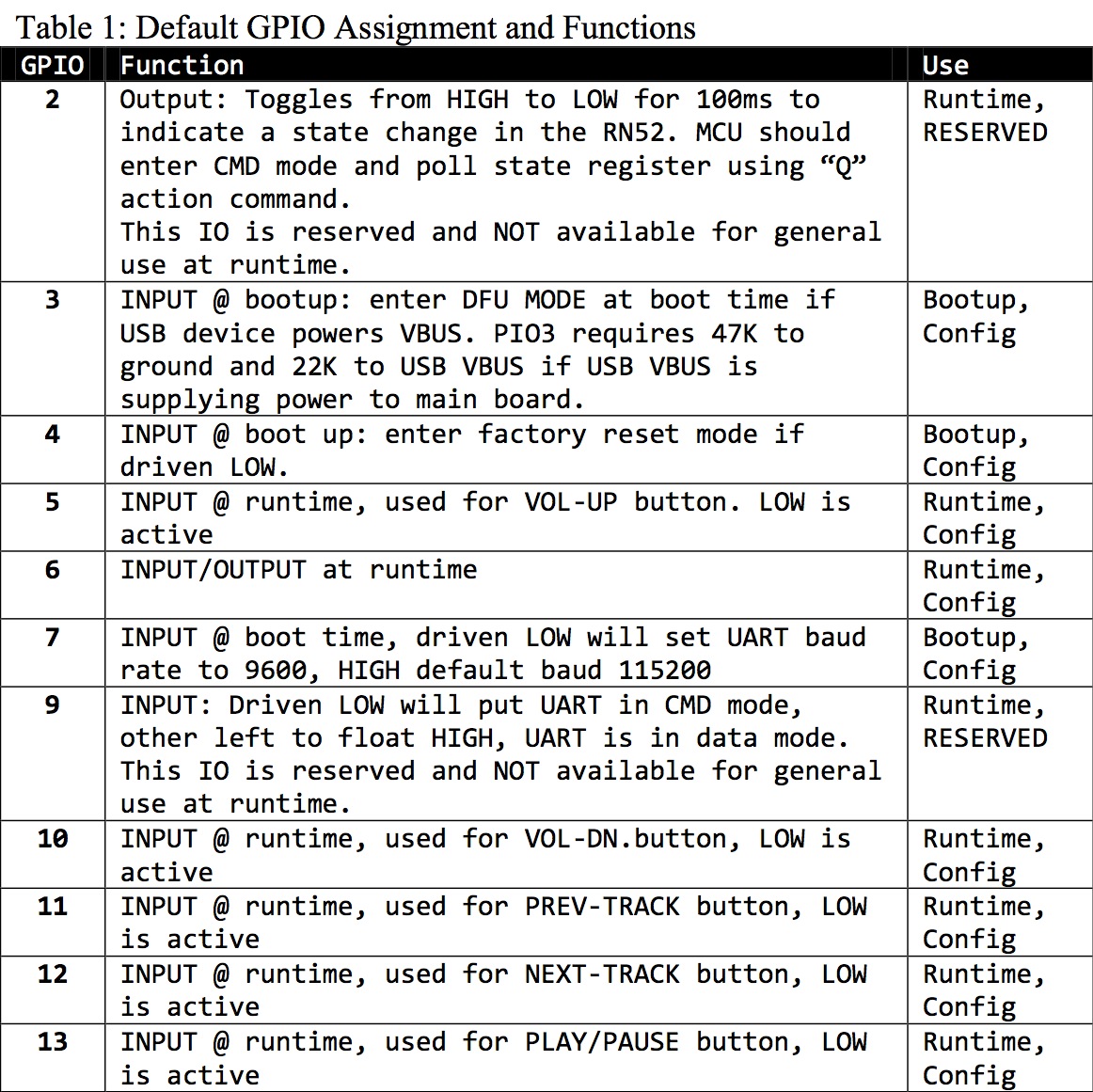
The most important pin to take note of is GPIO9. If you are familiar with other versions of Roving Network's Bluetooth modules, you may also be familiar with the $$$ command used to enter command mode on the module. On this module, however, there is only one way to enter command mode, by pulling GPIO9 LOW.
There is also one analog input/output line, AIO0.
3. USB
The USB lines are strictly used for device firmware update (DFU) mode. Used in conjunction with GPIO3, the USBD+ and USBD- lines allow you to upload new firmware directly to the RN-52.
4. UART
The UART lines are used to communicate with and configure the RN-52. Used in conjunction with GPIO9, the UART will allow you to send and receive serial commands to and from the module.
The UART can also be used to connect the module to an external microcontroller that issues commands and handles status updates.
5. Audio In/Out
These pins are reserved for audio input and output. The RN-52 comes ready to stream audio right out of the box. You can attach speakers directly to the speaker pins and get immediate gratification from wireless music. The RN-52 has a built in integrated amplifier capable of driving two 16Ω speakers or most standard headphones. The speaker outputs can also be attached to an external amplifier for greater amplification.
The RN-52 also supports audio input on the Mic pins.
6. Status LEDs
There are two status LEDs located on the breakout board. However, if you wish to place the board in an enclosure, these lines are broken out for external LEDs. The LEDs are configured as open drain output, meaning that they must be driven HIGH to activate the the LED.
| LED0 | LED1 | Description |
| Flashing | Flashing | The RN52 module is discoverable. |
| Flashing | Off | The module is connectable. |
| Off | Flashing | The module is connected. |
Note: Flashing refers to the LEDs flashing alternatively. If you see the LEDs flashing in unison, then you are in DFU mode. Please check pin 3 if you have entered DFU mode by accident.
7. SPI
External audio codecs can be sent over the SPI lines.
8. PCM
Another option for communicating with the module is the Pulse-Code Modulation (PCM) pins. PCM is a way to digitally represent sampled analog signals. This is done over an I2S connection. External audio codecs can be sent over these lines as well.
Hardware Setup
Before you can configure the module, some hardware needs to be connected. This section will cover the necessary hardware needed to work with the RN-52.
Materials Needed
Aside from an RN-52 Breakout, you will need the following:
Wiring the RN-52
In order to use the RN-52, you must first decide how you will connect external hardware to the breakout board. One option is to solder female headers to both sides of the breakout. Second, you can solder wire directly to the breakout. Another option, and the one that will be used in all the demos in this tutorial, is to solder straight male headers to the breakout so that it can be used in a breadboard.
*Note: The RN-52 breakout is too large to fit on a standard breadboard. Thus, you will need to attach two breadboards side by side.
*Note: The antenna on the RN-52 is very sensitive to interference. When placing the breakout on a breadboard, be sure that the antenna is hanging off the breadboard as far as is will go. This will prevent the metal inside the breadboard from interfering with the range of the module. Keep this in mind if you are designing your own PCB as well.
Power
First and foremost, the RN-52 is a 3.3V device. It can handle an input voltage of about 3.0 - 3.6V. Voltages above or below this range can result in the module not working properly or, worse, damaging the module. Make sure you select a power supply that can provide the correct amount of voltage to the device.
In this example, we'll be using an Breadboard Power Supply to provide 3.3V to the breakout. If you would like to power the breakout with a battery, make sure the battery can provide the correct amount of voltage. We recommend using a LiPo Battery in conjunction with the LiPower board set for 3.3V.
As usual, connect the GND pin to GND, and connect the 3.3V pin to the Vcc pin on the supply. That just leaves the power enable pin (PWR_EN). This can be hooked up one of two ways. The first method is to simply jumper the PWR_EN pin to 3.3V. This will cause the module to start up immediately once it is powered.
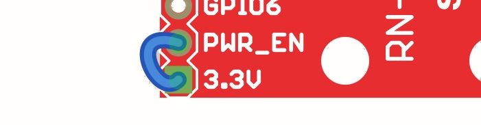
The PWR_EN pin can also be attached to a button to allow the user to power up the module when it is desired, even if power is already supplied. This is useful in headset/hands-free applications where a battery is attached to the module but the module doesn't need to be on all the time.
GPIO9
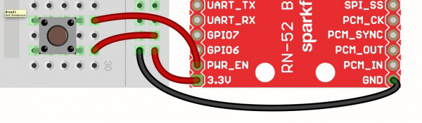
GPIO9 is used to tell the module to enter command mode. If GPIO9 is HIGH or left floating, the module will remain in its default data mode, streaming audio or data. In order to enter command mode, GPIO9 must be pulled LOW. This can be accomplished by simply connecting GPIO9 to GND with a jumper wire. In this example, a switch is used to easily enter and exit command mode.
UART
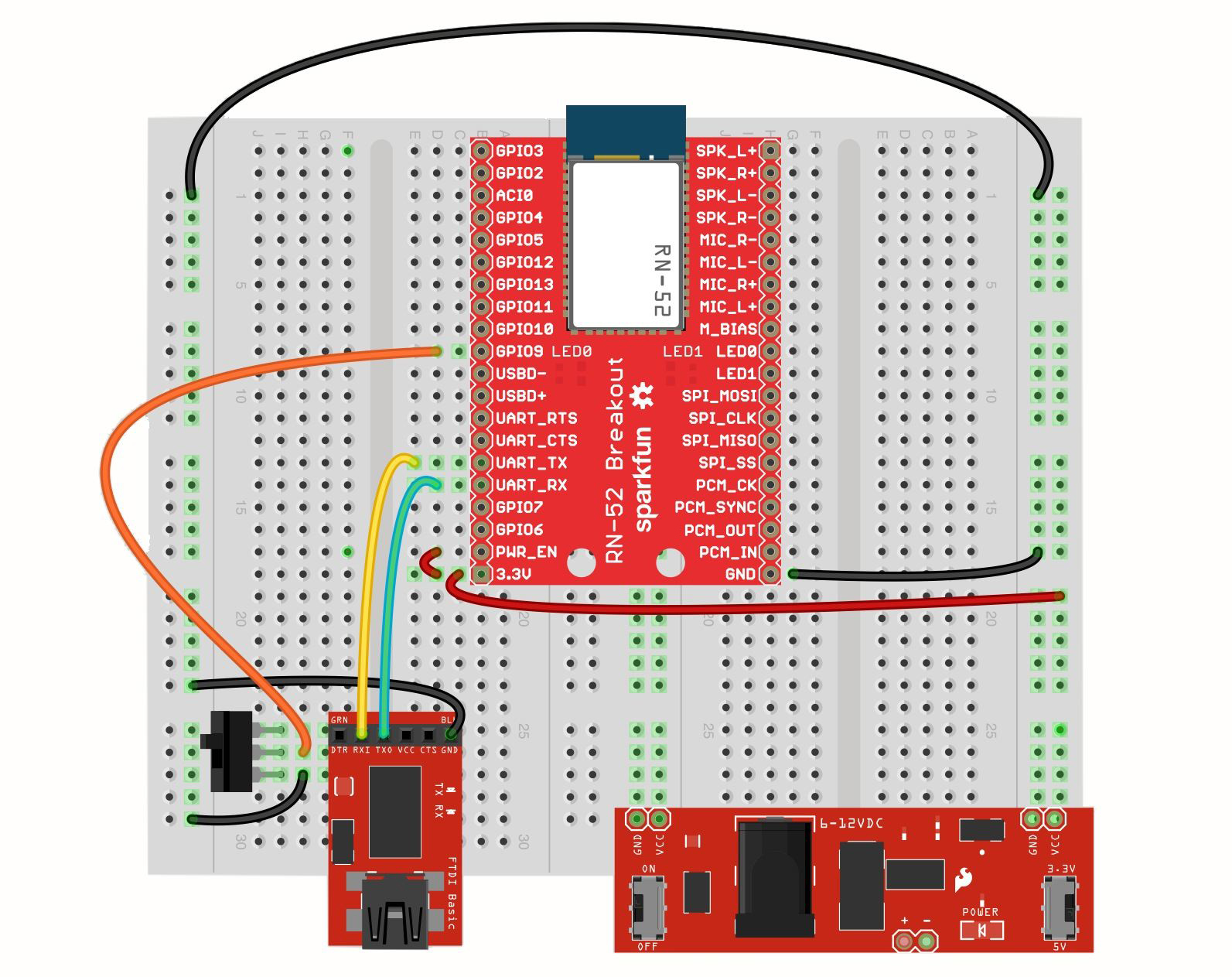
You will need a way to communicate to the module and send commands. This will be accomplished with a 3.3V FTDI Basic. Connect GND to GND, TXO to UART_RX, and RXI to UART_TX. Those are the only connections needed to talk to the module.
With that, you should have something that looks like this:
We're now ready to dive in and see how the RN-52 can be configured.
Configure the Module
Now that you can actually power up the RN-52 and send it into command mode, let's talk about changing the settings, and thus the behavior, of the Bluetooth module.
- Make sure the CMD Mode switch is in the OFF position (GPIO9 NOT shorted to GND).
- Turn on your RN-52.
- The two status LEDs should both stay solid for about 1 second and then begin flashing alternately.
- Your device is now ready to make a connection. Rather than connect over Bluetooth, the connection will be made over the serial UART.
- Open a terminal window on the port your RN-52 has been assigned (115200 Baud, 8,N,1).
- With the terminal open and connected to the RN-52, flip the CMD Mode switch to the ON position (GPIO9 shorted to GND). You should now see
CMDappear in your terminal.
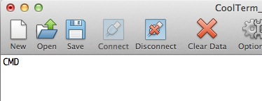
You are now in Command Mode!
To exit command mode, simply flip the switch back to the OFF position. You will see END appear in the window.
*Note: The RN-52 can enter and exit CMD mode _while_ streaming music.
Now let's explore the module's settings.
This portion of the tutorial will only briefly touch on the command set. To see a list of all the RN-52 commands, read the Command Reference User Guide.
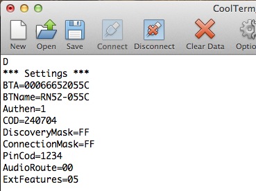
Get Commands
Get commands query the device for information.
D - Displays the basic settings such as name, address, pin code, etc.
Set Commands
Set commands change actual settings of the module such as name, profile mode, and extended features.
SN,\
SA,\
All set commands are followed by an AOK if the command was entered correctly and an ERR if it was not.
If you change any set commands, you must reboot the module before the settings will take effect. Type R,1(/r) to reboot the module.
Action Commands
Action commands tell the module what action to take. With these commands, you can accept incoming calls, change the volume, change the track, and pause your music. Check out the Command Reference for a complete list of action commands.
Troubleshooting
If you cannot talk to the RN-52 over the serial port, make sure you are connected at the correct baud rate (default:115200).
To change the baud rate, GPIO7 must be pulled LOW (it is HIGH by default). This will set the baud rate to 9600. 115200 and 9600 are the only two baud rates available on the RN-52.
If you need to implement a factory reset, send
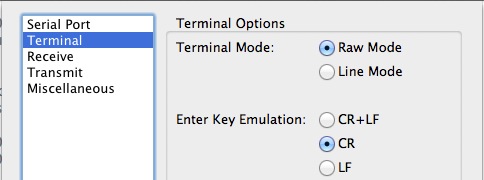
SF,1(/r)to reset the module, thenR,1(/r)to reboot it.The commands for the RN-52 all terminate with a carriage return (\r), not with a carriage return/line feed. If you keep seeing
?after every command you enter, there should be a setting in your serial terminal to turn on just carriage return.
This is especially important to note if you plan on having a microcontroller communicate with the RN-52.
Streaming Tunes
Enough talk. Let's stream some tunes! The RN-52 comes ready to begin streaming tunes from most any Bluetooth audio-capable device. However, to add external control functions such as play, skip, and volume, you'll need to make a few small adjustments.
Hardware
Using the same setup from the Hardware Setup section, let's add a few more pieces. By connecting a few buttons and some speakers, the RN-52 becomes a full-on music station and remote. The image below shows all the connections and the functions of each button.
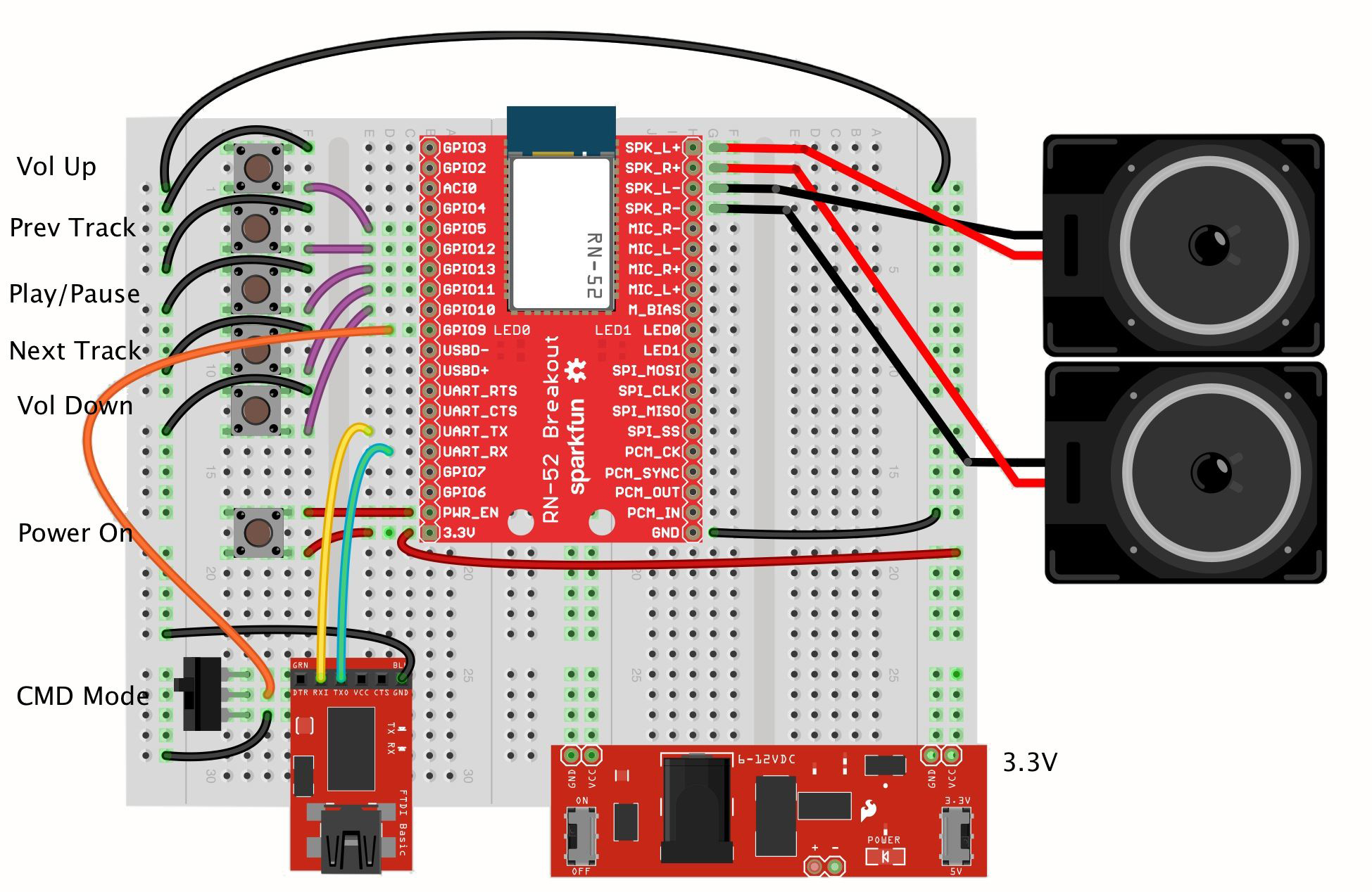
The functions for each GPIO can be found in the datasheet.
Configuration
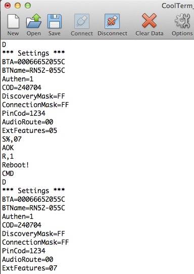
By default, the RN-52 does not have the AVRCP enabled. This is part of the extended features. When you type D to see the basic settings, you'll notice a line that says ExtFeatures=XX, where XX is some hex value. As of this writing, the default firmware comes with the AVRCP buttons disabled. Future versions of the firmware may differ. Looking in the Command Specifications document, we find this table:
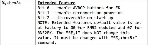
Notice that bit 0 is the bit we need to enable to activate the AVRCP button functionality. Send the command S%,07(/r) to enable this bit while leaving the other two bits enabled. Then follow it up with a reboot -- R,1(/r). You should now have AVRCP enabled. Type D to double check the settings.
That's really the only setting that needs changed for this example.
Connect and Play
You are now ready to connect to your Bluetooth device and start streaming some music. Directions on how to pair and connect to the RN-52 can also be found in section 1.4 of the user guide.
*Note: The quality of the audio will depend on which speakers you've attached. Testing the RN-52 with two 8Ω stereo speakers worked great. However, without external amplification, the volume needs to be cranked up to achieve normal indoor volume. If you're not satisfied with the volume, an external amp can be connected to the speaker pins. We recommend using the Audio Amplifier Kit.
Troubleshooting/Common Issues
Checking the Version Number
To check the version number of your RN52, you can use the “v” command. Make sure that you connect the 3.3V FTDI to the RN-52 as stated in the hookup guide for CMD mode: Rx <-> UART_Tx, Tx <-> UART_Rx, 3.3V <-> PWR_EN <-> 3.3V, GND<-> GND, and GPIO9 <-> GND. Using a serial terminal connected to the FTDI’s enumerated COM port (with setting 115200, 8-none-1-none). After typing the command, the RN-52 will respond with:
Ver 1.10 04/04/13
(c) Microchip Technology Inc.
Upgrading DFU Firmware over USB
Note: Upgrade at your own discretion before proceeding!!! You might brick your module if you are not cautious!!!
If you are interested in upgrading the firmware on the RN-52s, you will need the USBD+, USBD-, GND and GPIO3 pins. The standard default v1.10 firmware on the RN-52s requires DFU over USB. After flashing the v1.16 (file rn52-i_rm116.dfu ), the RN-52 will have the ability to use DFU over UART.
Try looking at the RN52 Firmware v1.16 Release Notes for new additional features.
1.) Head to Microchip’s RN-52 Product Page .
2.) Download the RN52 Bluetooth DFU Utility Installer located under “Documentation > Software.” This will contain the application called MicroChip Bluetooth DFU Utility Installer.exe and a guide called RN52-EK DFU Procedure Guide.pdf . The guide was written for Microchip’s RN52-EK development board but there was no issues updating RN-52’s on our breakout board.
3.) Download the image of your choice below the software. You have the option of using “RN52-I/RM110 DFU Image” (saved as the rn52-i_rm110.dfu file) or “RN52-I/RM116 DFU Image” (saved as the rn52-i_rm116.dfu file).
4.) Unzip Microchip Bluetooth DFU Utility Installer.zip .
5.) Click on the Microchip Bluetooth DFU Utility Installer.exe to install.
6.) Follow the installation instructions in the installer. This will also install the driver for your Rn-52 audio bluetooth though USB.
7a.) Hardware Connection Connect a DFU Over USB Pins: USBD+, USBD-, 3.3V, PWR_EN, GND, and GPIO3 pins. You could use the a USB Mini-B Breakout, mini-B cable , and jumper wires. Since I already connected the 3.3V FTDI to the RN-52, I just used 3.3V and GND from the FTDI to the RN-52 for power. Make sure to connect GND of the USB Mini-B breakout with the GND of the FTDI so the reference is the same:
USB Mini-B Breakout <=> RN-52 Breakout
D-                  <=>      USBD-
D+                  <=>      USBD+
GND                 <=>      GND

3.3V FTDI Basic Breakout <=> RN-52 Breakout
        3.3V             <=>    GPIO3
        GND              <=>    GND
7b.) Power Cycle Power cycle the RN-52 so that the GPIO3 is HIGH at boot time. The green LED labelled (LED0) and red LED labelled (LED1) will blink simultaneously.
7c.) Launch the the “Microchip Bluetooth Device Firmware Upgrade Utility” software (i.e. MCHPDFUUtility.exe ).
7d.) You will be greeted with a note from Microchip. Click on the “Next >” button to begin.
7e.) Connection Type Selection Select “DFU over Universal Serial Bus (USB)” and click on the “Next >” button.
7f.) The software should automatically search for the device that is connected over USB. Your computer might pop up with a new device (For Windows, there was a popup in the notifications):
CSR BlueCore in DFU Mode
7g.) Upgrade Action Selection Select “Download a new version of the firmware, saving a copy of the current version first. Any previous saved version will be replaced. (Recommended.)” and click “Next >”.
7h.) Upgrade File Select the location of your file (i.e. rn52-i_rm116.dfu ). and click “Next >”.
7i.) Ready to Upgrade Verify your selections and click “Next >”. Your window might say something like this:
USB device:
        HUB5_PORT2(BD_ADDR = ??-??-??-??-??-??)

Upload:
        Existing firmware will be saved

Download:
        C:\Users\...\Desktop\RN52saved\rn52-i_rm116.dfu
Note: Since the PWR_EN is connected to 3.3V already, you do not need to “hold the power button down” as stated in the guide for Microchip’s RN52-EK development board. The upgrade automatically started as soon as I pressed on the “Next >” button.
7j.) Upgrade in Process Make sure to not interrupt the power and connections during the firmware upgrade. There will be progress bars that indicate your progress. Depending on your upgrade selection, it will save the previous firmware, flash the new firmware, and verify the update on the RN-52.
7k.) Successful Upgrade Once finished, the utility will provide the total time it took to save your file and flash the new firmware. It took less than 5 minutes to upgrade the firmware:
.
.
.
Time Taken:
    Upload    00 minutes 24 Seconds
    Download  03 minutes 06 seconds
There was also a verification process after flashing the new firmware. This should take about a minute to complete. Click “Finish” to complete the upgrade at the final screen.
7l.) Cycle Power Disconnect GPIO3 from 3.3V so that it is LOW. Power cycle the RN-52 by disconnecting and reconnecting power to 3.3V.
8.) If you are already connected to a serial terminal with a 3.3V FTDI and the RN-52 set to CMD mode, you can verify the version number by sending the “v” command. The RN-52 should respond with this output:
RN52-I Ver 1.16 (c) Microchip Technology Inc.
This should indicate that the firmware has been upgraded to the new firmware. Try testing out the new firmware by playing music from a smartphone. =)
Streaming Music and Phone Calls
When streaming music with the audio bluetooth and a call comes in, the smartphone will automatically stop the music and begin to ring until the call is answered/rejected. After answering or rejecting the call, the music will begin to stream again.
Useful mic design application notes for the RN-52
http://www.jenrathbun.com/Electronics/rn52-bluetooth-adapter-microphone/
Resources and Going Further
Wireless music, how sweet it is! We've only just scraped the surface of what the RN-52 is capable of. Try your hand at a project that incorporates the RN-52. You could create your own wireless headset. You could have a home theater system that can stream music from your mobile device. You could even connect an RN-52 to your car stereo and stream tunes from your phone as you travel. The possibilities are endless!
Resources
Here are all the documents listed in this tutorial:
Also, don't forget to check out the RN-52 GitHub page for all the hardware files and info.
This site is a handy Bluetooth Class of Device (CoD) generator.
For more tutorial action, check out these related tutorials: