RN-52 Bluetooth Hookup Guide
The RN-52 Breakout
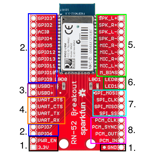
There is a lot going on with the RN-52 breakout board. Let's break it up into sections to find out what pins are needed for what purposes.
1. Power
Powering the RN-52 is very simple. There are three pins necessary to power the board, 3.3V, GND, and power enable (PWR_EN). The supply voltage should be in the 3.0 ~ 3.6V range.
2. GPIO Pins
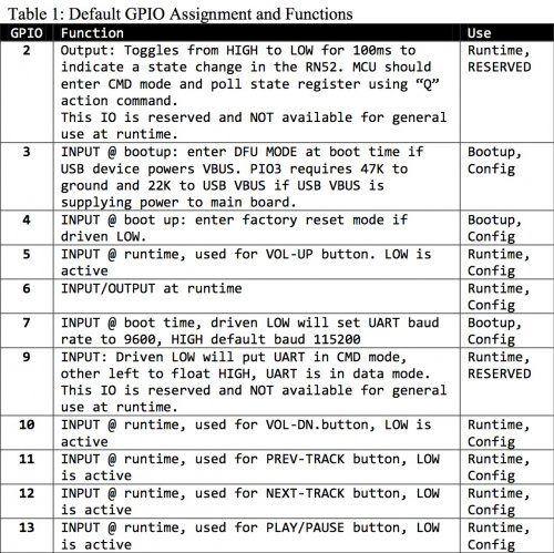
The RN-52 has eleven general purpose input/output pins (GPIO). Many of these pins are reserved for special functions when the module is booted up and when the module is running. These pins also act as input pins for specific functions during audio playback. These can be configured to control media programs such as iTunes or Windows Media Player (eg. Play, Pause, Next Song, etc.).
The most important pin to take note of is GPIO9. If you are familiar with other versions of Roving Network's Bluetooth modules, you may also be familiar with the $$$ command used to enter command mode on the module. On this module, however, there is only one way to enter command mode, by pulling GPIO9 LOW.
There is also one analog input/output line, AIO0.
3. USB
The USB lines are strictly used for device firmware update (DFU) mode. Used in conjunction with GPIO3, the USBD+ and USBD- lines allow you to upload new firmware directly to the RN-52.
4. UART
The UART lines are used to communicate with and configure the RN-52. Used in conjunction with GPIO9, the UART will allow you to send and receive serial commands to and from the module.
The UART can also be used to connect the module to an external microcontroller that issues commands and handles status updates.
5. Audio In/Out
These pins are reserved for audio input and output. The RN-52 comes ready to stream audio right out of the box. You can attach speakers directly to the speaker pins and get immediate gratification from wireless music. The RN-52 has a built in integrated amplifier capable of driving two 16Ω speakers or most standard headphones. The speaker outputs can also be attached to an external amplifier for greater amplification.
The RN-52 also supports audio input on the Mic pins.
6. Status LEDs
There are two status LEDs located on the breakout board. However, if you wish to place the board in an enclosure, these lines are broken out for external LEDs. The LEDs are configured as open drain output, meaning that they must be driven HIGH to activate the the LED.
| LED0 | LED1 | Description |
| Flashing | Flashing | The RN52 module is discoverable. |
| Flashing | Off | The module is connectable. |
| Off | Flashing | The module is connected. |
Note: Flashing refers to the LEDs flashing alternatively. If you see the LEDs flashing in unison, then you are in DFU mode. Please check pin 3 if you have entered DFU mode by accident.
7. SPI
External audio codecs can be sent over the SPI lines.
8. PCM
Another option for communicating with the module is the Pulse-Code Modulation (PCM) pins. PCM is a way to digitally represent sampled analog signals. This is done over an I2S connection. External audio codecs can be sent over these lines as well.

