RETIRED - MG2639 Cellular Shield Hookup Guide
This Tutorial is Retired!
This tutorial covers concepts or technologies that are no longer current. It's still here for you to read and enjoy, but may not be as useful as our newest tutorials.
Introduction
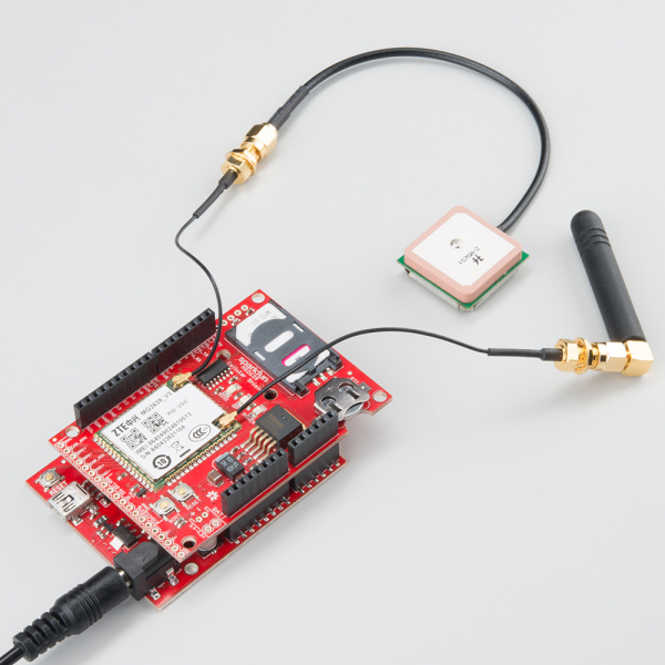
The MG2639 Cellular Shield is a perfect addition to any Arduino project that requires connectivity when there's no WiFi signal radiating or Ethernet drop nearby. The ZTE MG2639 module, which this shield is built around, supports SMS, TCP, UDP, and can even be used to make or receive phone calls (imagine that!). That means you can send and receive text messages, or use it to remotely connect your Arduino to the Internet. To top it off, it has an integrated GPS receiver, so it doesn't get lost.
The MG2639 Cellular Shield is the perfect centerpiece for any remotely-operating project -- whether it's a text-message-triggered MP3 player, an environmental monitor logging to data.sparkfun.com, or a new iteration of the Port-O-Rotary telephone.
Covered In This Tutorial
This tutorial aims to answer any and every question you have about the MG2639 Cellular Shield. In the beginning, we'll focus on the hardware of the board -- looking at the schematic, pin-outs, and jumpers on-board. Then we'll discuss what assembly steps to take before connecting the shield to your Arduino -- finding the right power supply, plugging in a SIM card, and so on. Finally we'll show off the MG2639 Arduino library and document a series examples that demonstrate how to use the module's TCP, SMS, and phone functionalities.
This tutorial is split into sections. Click the links to the right if you want to jump around to other sections.
Required Materials
Aside from the MG2639 Cellular Shield itself, there are a few extra components you'll need to connect it all up. Here's a list of recommended products which we will use in this guide:
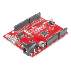
- SparkFun RedBoard -- You'll need a "brain" to control the cellular shield. It should work with any Arduino board with the "standard" footprint -- Arduino Uno, Arduino Leonardo, Arduino Pro, etc.
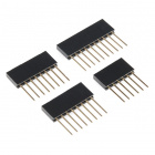
- Stackable Headers -- Solder these to you shield so it can connect to your Arduino.
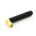
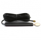
- Cellular Antenna -- For the MG2639 to connect to a network, it needs an external antenna.
- SMA to U.FL Adapter -- The MG2639 only has U.FL antenna ports, so if your antenna has an SMA connector (like the one above) you'll need an adapter.
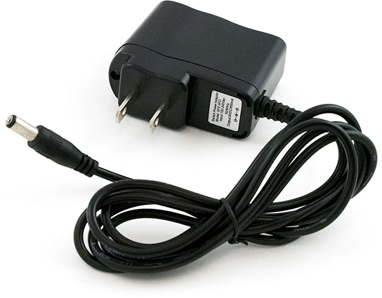
- 9V Power Adapter -- The MG2639 Shield requires more power than an Arduino can supply when it's powered over USB. We recommend this 9V wall adapter, but any power supply within your Arduino's specified input voltage range should work.
- SIM Card -- You'll need access to a cellular provider's network. Any activated, full-size SIM card should work. You should be able to buy any "burner" phone and yank out the SIM card.
Wall Adapter Power Supply - 9VDC 650mA
TOL-00298Beyond those items, here are some optional components you may want to add as well:
- GPS Antenna -- If you want to take advantage of the MG2639's GPS features, you'll need to connect a second antenna rated for GPS signals. We're working on sourcing a good, U.FL antenna for the MG2639. In the meantime, we've had success with the this Tagolas GPS antenna.
- 12mm Coin Cell Battery -- The shield includes a socket for a 12mm coin cell battery -- used by the on-board GPS module to retain location memory and enable faster location fixes.
- Speaker and Microphone -- If you want to turn the MG2639 Shield into an actual cell phone these become pretty important.
Suggested Reading
Before delving into this guide, there are a few subjects you should be familiar with. Here are some tutorials you may want to check out before continuing on:
- Serial Communication -- Both the cellular and GPS modules communicate with your Arduino over a serial UART.
- Arduino Shields -- Explore all things Arduino Shields. What they are and how to assemble them.
- Installing an Arduino Library -- We've written an Arduino library for this shield, if you've never installed a library before, check this guide out.
Hardware Overview
Before you get to connecting the MG2639 Cellular Shield to your Arduino, you should familiarize yourself with the features and abilities of the board. This page serves as an overview of the shield's components and pin-outs. It also looks at some of the "hidden" features of the board.
Component Overview
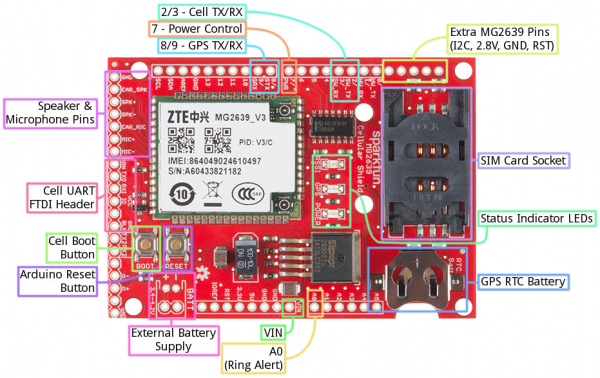
For a quick overview, here are most of the components of interest on the shield:
Arduino Pins Used
One of the most important characteristics of a shield are the Arduino pins used, here's a list of the pins used by the cellular shield:
| Arduino Pin | MG2639 Function | Notes |
|---|---|---|
| VIN | Power Supply | The MG2639 requires that the Arduino be supplied with an external power source (USB won't cut it). This pin is disconnectable via a jumper. |
| A0 | RING Alert | This pin will go low when a phone call is coming in. |
| 2 | Cell UART TX | Cell module's data output (4800 baud). |
| 3 | Cell UART RX | Cell module's data receive (4800 baud). |
| 7 | Cell boot pin | This pin has the same control over the module as the BOOT button (explained below). |
| 8 | GPS UART TX | GPS module's data output (115200 baud). |
| 9 | GPS UART RX | GPS module's data receive. |
Cell and GPS UARTs
Communication with the cellular and GPS module's occurs on two separate serial UARTs. To leave the Arduino's hardware UART free for debugging and uploading sketches, both UARTs are broken out to digital pins -- intended for use with the SoftwareSerial library.
Because the SoftwareSerial library can't reliably support high-ish baud rates, we've intentionally slowed down the MG2639's cellular UART to 4800 bps, rather than the module's default bit rate of 115200. This slower rate ensure data reliability, and gives the Arduino some extra time to process large strings.
The GPS UART is hard-coded to 115200 baud, which make it harder to use with SoftwareSerial. Instead, we recommend using the AltSoftSerial library with this part of the module.
Either of the two UARTS (the cell or GPS) can be switched over to the Arduino's hardware UART. Check out the "Jumpers" section below for more information.
LED Status Indicators
There are a trio of LEDs on the MG2639 Cellular Shield which indicate connectivity or power status:
- POWER -- This red LED is connected to the MG2639 module's power supply line. If this LED is on, the module is receiving power.
- RSSI -- This green LED indicates the status of your cellular network. It'll blink at various rates to show what state it's in:
- OFF -- The module is powering on (assuming it has power).
- 1 Hz blink -- Module is idle.
- 3 Hz blink -- Searching for a network.
- 5 Hz blink -- Module is in a traffic state (a phone call or data transmission).
- GPS -- GPS fix indicator. This yellow LED will illuminate when the MG2639's GPS module gets a solid fix.
Boot & Reset Buttons
Two buttons labeled "BOOT" and "RESET" are built into the shield. The "RESET" button is simply the Arduino reset, it'll have no direct effect on the MG2639.
The "BOOT" button connects to the MG2639's PWRKEY input, which turns the module on or off. This button works exactly as you might expect any cell phone power button to work. If the module is off, hold the button down for 2-5 seconds then release to turn it on. If the module is on and you hold the button down and release, it'll turn off.
Control of this button is shared between the physical button itself and Arduino pin 7. The Arduino pulling pin 7 LOW has the same effect as pushing the button down. This gives the Arduino machine control over the module's ON/OFF status.
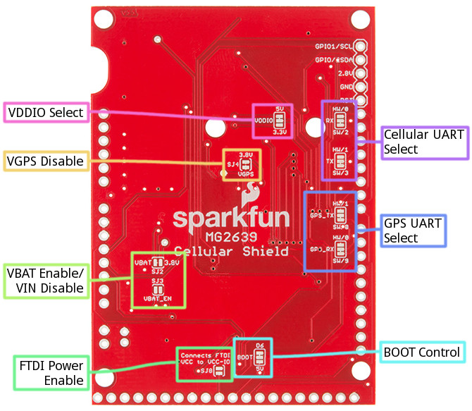
Bottom-Side Jumpers
To keep the Shield as multi-purpose as possible, there are a number of jumpers on the backside that can be used to switch the interface pins or power supply.
To open any of these jumpers, use a hobby knife, and remove the small trace between any two connected pads. To connect a jumper, solder a small solder joint between two pads.
Here's a quick rundown of each jumper:
- VDDIO -- This jumper selects the voltage for logic running into the high side of the shield's TXB0104 level shifter. It defaults to 5V but can be switched to 3.3V if your application requires.
- Cellular UART RX and TX -- These jumpers allow you to switch the cellular module's RX and TX between either pins 2 and 3 or 0 and 1. That means selecting between a software (2/3) or hardware (0/1) UART.
- GPS_TX and GPS_RX -- Like the other UART jumpers, these allow you to set the GPS module's UART to either software (8/9) or hardware (1/0).
- VGPS Disable (SJ4) -- This jumper controls power delivery to the shield's GPS module. If you don't want to use the MG2639's GPS module, and want to avoid the power loss it incurs, cut this jumper.
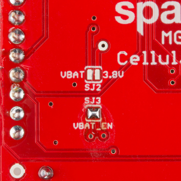
- VBAT Enable/Disable (SJ2 and SJ3) -- If you want to power the Cellular Shield from a single-cell lithium polymer battery, you'll need to attack both of these jumpers. Shorting SJ3 will connect the JST-footprint connector directly to the module's power supply. Opening SJ2 will disconnect the voltage regulator output from the rest of the circuit.
- FTDI Power Enable (SJ8) -- If you want to use an FTDI Basic to troubleshoot the MG2639's UART, this jumper will allow you to power the VDDIO line with the FTDI's VCC pin.
- BOOT Control -- This jumper allows you to remove Arduino pin 7 (mislabeled "6" near the jumper) from the MG2639's boot button.
Note: If you decide to use the hardware UART, make sure to only connect one of the two modules to the 0/1 pins! If both are connected, bus contention and data loss will occur.
Hardware Assembly
Now that you're familiar with the components and inner workings of the MG2639 Cellular Shield, it's time for some assembly!
Soldering
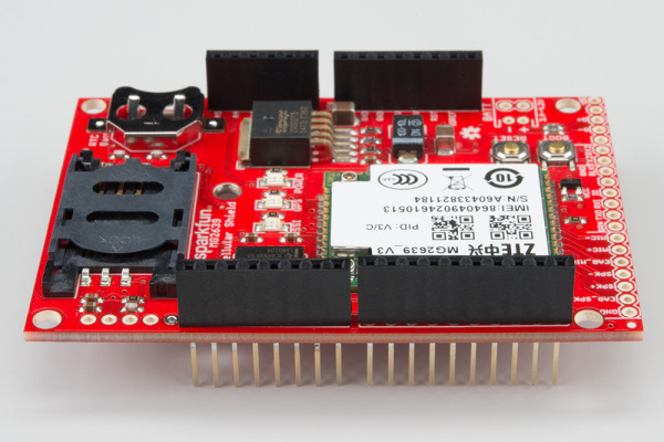
You'll need to solder a header of some kind to the shield, in order to connect it to your Arduino. Stackable headers are always a popular option as they allow you to plug additional shields or jumper wires into your Arduino's unused pins.
You can also instead use male headers to connect it to the Arduino. If you're looking to use the shield as more of a breakout board, you can solder wires directly to the pins you need.
For more help with shield assembly, check out our Shield Assembly Guide.
Antennae
Both the cellular and GPS functions of the MG2639 require an external antenna connected to the module. There are two U.FL connectors on the side of the chip -- one labled "GSM" the other "GPS."
Any of the quad-band cellular antennas below will work with the shield, but you'll need a U.FL to SMA adapter to complete the connection.
We're working on sourcing a good antenna for the MG2639. We've had success with this patch antenna from Tagolas.
SIM Card
One of the hardest parts in getting the shield to work is finding a suitable network and SIM card to run it on. You may be able to find a sweet, contract-free deal like our T-Mobile 6-month Unlimited card.
Another option is to pick up a prepaid "burner" phone -- like a Go phone -- and swap the SIM card into the shield.
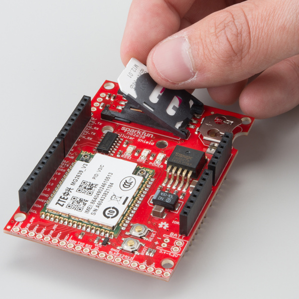
The workings of the SIM card socket can take some getting used to. To unlock the latch, push the top part of the assembly towards the battery, then lift it up. Slide the SIM card into the moving part of the socket with the SIM's notch pointing away from the battery holder.
Then fold the arm back into the body of the socket, and gently push it forward towards the "LOCK" position.
Connecting a Speaker and Microphone
To use the MG2639 as a cell phone, you'll need to add some external bits of hardware. The audio port, on the end of the shield, allows you to hook up a speaker and microphone directly to the MG2639's audio interface. The audio port has six pins broken out for speaker, earpiece, and/or microphone hardware. These pins are labeled:
- EAR_SPK -- "Earpiece" speaker. This is a single-ended audio output with 32 Ω impedance. If using this interface, the other pin of the speaker should be connected to ground.
- SPK+ and SPK- -- Differential speaker interface. If using this interface, the two pins of a speaker can be tied directly to these two pins.
- EAR_MIC -- "Earpiece" microphone. This is a single-ended audio input. If you use this interface, connect the other microphone pin to ground.
- MIC+ and MIC- -- Differential microphone input. If you're using this interface the two microphone pins can be connected directly to these pins.
There are a variety of speakers and microphones that can be connected to these pins. If you just want to try a simple proof-of-concept, you can use our Electret Microphone and Thin Speaker to test the interface out.
Section 4.4 of the MG2639 Hardware Development Guide includes some excellent information about connecting an audio interface to the MG2639. Consult that document for more information about the impedances, offset voltages, and sensitivities.
Supplying Power
Beyond finding a suitable SIM card, the most important part of getting the MG2639 Shield working is supplying it with enough power.
Power Supply Requirements
Depending on which state it's in, the MG2639 module can be a relatively power-hungry device. The maximum current draw of the shield is around 350mA. It usually won't pull that much, but may require around 260mA during phone calls or 80mA during network transmissions. This chart from the datasheet summarizes what you may expect:
In selecting your power supply, it's important to note that the MG2639 Shield will not work if your Arduino is only powered off USB -- an external power supply is required to power both the Arduino and Shield. The shield includes a 3.8V regulator to supply the MG2639 within its 3.4-4.2V range. That regulator is sourced by the Arduino's VIN pin. We recommend a barrel jack power supply with a voltage output in the acceptable range of your Arduino (or at least 4.5V for the shield).
Our 9V power supply is a good choice, and the one we used in our prototyping and testing.
(Optional) Using a Battery Supply
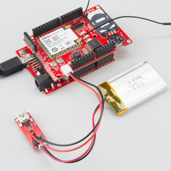
The operating voltage range of the MG2639 (3.4-4.2V) makes it an ideal candidate for direct LiPo battery supply. The Shield can be powered through a LiPo battery, but there are some adjustments you'll need to make to the bottom-side jumpers before doing so.
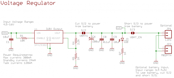
As a starting point, here is the schematic of the shield's voltage regulator and power input circuitry:
In order to power off a battery instead of the Arduino's VIN pin ("VRAW" on the schematic), you need to cut SJ2 and short SJ3.
SJ2 will prevent the 3.8V regulator from supplying a competing voltage to the battery. SJ3 will allow the battery to directly supply the MG2639.
To connect the battery to the shield, two connectors are broken out on the top side of the board, labeled "BATT". One connector is a footprint for our 2-Pin JST Connectors, which mates with our catalog of single-cell LiPo's. The other is a simple 0.1" 2-pin header.
The battery supply will not be fed back into the Arduino, so you'll need to either find a separate power supply for the microcontroller board, or split the battery in two directions.
Installing and Using the Arduino Library
Now that all of the nitty-gritty hardware stuff is out of the way, it's time to get to some Arduino coding! First, we'll get you set up with the SFE_MG2639_CellularShield library, then we'll delve into some example sketches.
(That release of Arduino included an improved version of the SoftwareSerial library, which the Cellular Shield library depends on.)
Download and Install the Arduino Library
We've written an Arduino library specifically for the MG2639 Cellular Shield. Click the button below to download it, or clone it from our GitHub repository.
For help installing the library, please check out our Installing an Arduino Library tutorial. You'll need to copy the library into a "libraries" folder within your Arduino sketchbook.
Try the MG2639_GetInfo Example
To prove that your cellular shield is working, try running the most simple example sketch included with the library. MG2639_GetInfo.ino is a simple sketch that turns the shield on, verifies communication with it, and prints all sorts of information like your CIMI, ICCID, and phone number.
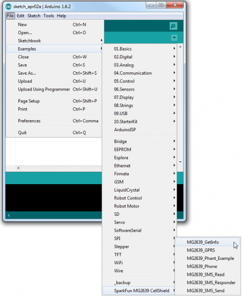
Open the sketch by going to File > Examples > SparkFun MG2639 CellShield > MG2639_GetInfo.
Then, after verifying that your SIM card, antennas, and power supply are all connected, upload the sketch.
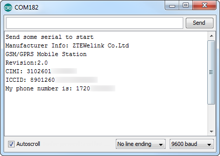
To actually set the sketch into motion, open up your serial monitor and send any character. After a few moments, the monitor should respond with a number of information tidbits about your shield:
The sketch will finish faster if you turn the module on before running it. Try holding down the "BOOT" button until you see the "RSSI" blink steadily at 1Hz. It's a good idea to play with the BOOT button until you have a good idea of how it controls the module.
Using the Library: Initialization
This example introduces a handful of functions and code lines you'll become very familiar with as you use the library. To begin, make sure you include the "SFE_MG2639_CellShield" library at the top of any sketch. The library also makes use of the SoftwareSerial library, which you'll need to include as well.
language:c
// The MG2639 library uses the SoftwareSerial library, and
// requires it to be included first.
#include <SoftwareSerial.h>
// Include the SFE_MG2639_CellShield library to access
// the cellular functions.
#include <SFE_MG2639_CellShield.h>
To begin communication the cellular module, and perform some set up, call the cell.begin() function. This initializing function will return with the status of the module after exit -- if it returns 1 the module is on, communicating, and ready to go. If it returns 0 the module is not communicating with the Arduino for some reason.
language:c
// Run cell.begin() to initialize communication with the
// module and set it up.
uint8_t status = cell.begin();
if (status <= 0)
{
// If begin() returns 0 or a negative number, the Arduino
// is unable to communicate with the shield. Make sure
// it's getting enough power. Try again making sure the
// MG2639 is booted up before running the sketch.
  Serial.println("Unable to communicate with shield.");
  while(1)
    ;
}
If your Arduino is not communicating with the module, try turning it on manually (via the BOOT button) and running the sketch again. If that fails, make sure you have enough power supplied to the shield -- the RSSI LED should be steadily blinking at 1Hz after turning on. If you're still not having any luck communicating with the module, get in touch with our tech support team and give them as much information about your setup as possible.
The most important piece of information you'll need is probably your phone number, if you don't already know it. You can use the cell.getPhoneNumber(char * phoneNumber) function for this purpose. For example:
language:c
// getPhoneNumber requires one parameter - a char array
// with enough space to store a phone number (~15 bytes).
// Upon return, cell.getPhoneNumber(myPhone) will return
// a 1 if successful, and myPhone will contain a char array
// of your module's phone number.
status = cell.getPhoneNumber(myPhone);
if (status > 0)
{ // If the function successfully returned, print the #:
  Serial.print("My phone number is: ");
  Serial.println(myPhone);
}
Getting the module's CIMI, ICCID, and other information follows a similar pattern of passing an array by reference. Consult the comments in the sketch for help using those functions.
Example 1: Text Messages
The library includes a fun example sketch the demonstrates how to send and receive text messages. If your cellular plan has SMS-ability, give the MG2639_SMS_Responder example a try!
With the SFE_MG2639_CellularShield library installed, open the sketch by going to File > Examples > SparkFun MG2639 CellShield > MG2639_SMS_Responder.
You shouldn't have to change anything here, simply upload the sketch to your Arduino/shield combo.
Running the Example
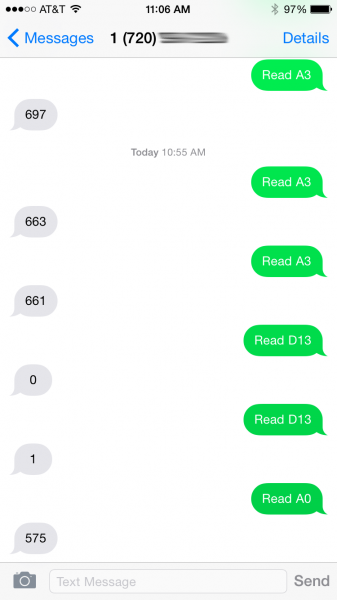
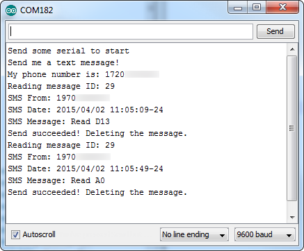
The purpose of this example is to demonstrate how to receive text messages, act upon them, and send an SMS of our own. If the Arduino receives an expected text message string, it'll respond with a sensor reading. For example, if you send a text message saying "Read A0" (like that, case-sensitive), the Arduino will send a text message back containing the current analog voltage on A0. "Read D13" will return the digital value of D13 -- 0 or 1.
As with the previous example, to start the sketch, open your serial monitor, and send any character. The Arduino will poll the shield for its phone number, then ask you to send a text message.
Any text messages received will be printed out to the Serial Monitor along with the sending phone number and date.
If the text of the message matches one of the strings we're looking for, the Arduino will send an SMS back to the sender with the desired information.
Using the Library: SMS
To use the SMS functionality of the library, there is a second object defined as sms. There are a variety of functions available to the sms class, here's a quick overview:
Setting SMS Mode
sms.setMode(sms_mode) sets the SMS mode of your cell shield. You can either set the SMS mode to SMS_PDU_MODE (pure data mode) or SMS_TEXT_MODE (text strings). More often than not you'll want to use SMS_TEXT_MODE to read and send SMS. This must be set explicitly before using the sms functions!
Checking for available message
An sms.available(sms_status) function is defined for you to check if any read and/or unread messages have been received. The value returned by this function may not be what you expect, though -- it returns the index of the first requested message. Every message stored in the module is assigned an index number. The index is important because it identifies which message you want to read later on.
sms.available() expects one parameter, it can be any of:
sms.available(REC_UNREAD)-- Returns the index of the first unread message.sms.available(REC_READ)-- Returns the index of the first read message.sms.available(REC_ALL)-- Returns the index of the first read or unread message.
If sms.available() doesn't find any of the requested message type, it will return 0.
Reading an SMS
After calling sms.available() and finding a message index to read, use sms.read(index) to read it.
Aside from an error code (1 for success, negative number for an error), sms.read() doesn't return the message. Instead use sms.getMessage(), sms.getSender(), and sms.getDate() to read the message, sending phone, and timestamp the message was sent. These values are only updated after an sms.read().
Here's an example based on the sketch:
language:c
// Get first available unread message:
int messageIndex = sms.available(REC_UNREAD);
// If an index was returned, proceed to read that message:
if (messageIndex > 0)
{
    // Call sms.read(index) to read the message:
    sms.read(messageIndex);
    Serial.print(F("Reading message ID: "));
    Serial.println(messageIndex);
    // Print the sending phone number:
    Serial.print(F("SMS From: "));
    Serial.println(sms.getSender());
    // Print the receive timestamp:
    Serial.print(F("SMS Date: "));
    Serial.println(sms.getDate());
    // Print the contents of the message:
    Serial.print(F("SMS Message: "));
    Serial.println(sms.getMessage());
}
The strings in these "get" functions will remain intact until you call sms.read() on a different index.
Sending an SMS
There are at least three steps to sending an SMS message: sms.start(phoneNumber), sms.print(message), and sms.send(). All three are required to send any message. sms.start(phoneNumber) indicates that you're beginning to write a message and sets the destination phone number. sms.print() can be used to send any data type -- string, integer, float, you name it in the body of the text. Just take care not to send anything besides sms.print() between your start() and send() calls.
Here's an example usage:
language:c
sms.start(sms.getSender());
sms.print("Analog 0 is: ");
sms.print(analogRead(A0));
int8_t status = sms.send();
if (status > 0)
    Serial.println("SMS successfully sent");
Deleting a Stored SMS
Due to limitations of the library and the Arduino's memory, we can only keep track of so many (256 by default) unread messages. If you can stomach letting them go, we recommend using the deleteMessage(index) function to remove a message from a SIM card's memory whenever possible.
To use the deleteMessage() function, simply supply the index of your message as a parameter. For example, to delete a message after you've read it:
language:c
// Get first available unread message:
int messageIndex = sms.available(REC_UNREAD);
// If an index was returned, proceed to read that message:
if (messageIndex > 0)
{
    // Call sms.read(index) to read the message:
    sms.read(messageIndex);
    Serial.println(sms.getMessage());
    // Delete the message after reading:
    sms.deleteMessage(i);
}
A second example in the library -- MG2639_SMS_Read -- allows you to go through the logs of your text messages and delete any or save them.
Example 2: GPRS & TCP
One of the most powerful aspects of the MG2639 is its ability to connect to a GPRS network and interact with the Internet. The module supports TCP/IP, DNS lookup, and most of the features you'd expect from a similar WiFi or Ethernet shield.
There are a couple examples demonstrating GPRS and TCP in the SFE_MG2639_CellularShield library. Open up the general example -- MG2639_GPRS -- by going to File > Examples > SFE_MG2639_CellularShield > MG2639_GPRS.
Running the Example
This example demonstrates how to turn the MG2639 into a simple browser client. It shows off most of the GPRS functions, including enabling GPRS, finding local and remote IP addresses, connecting to a server, and sending/receiving data.
A char array near the top of the sketch -- const char server[] = "example.com"; -- defines the remote URL your shield will try to connect to.
As with the other sketches, after uploading the sketch, run it by opening the serial monitor and sending any character. The MG2639 will open GPRS, find its IP, find the destination IP and send an HTTP GET request.
After sending a simple HTTP GET request to the server, the shield will print any response from that server back to the serial monitor.
Using the Library: GPRS
As with SMS, an entirely different class is defined for GPRS capabilities. These functions are preceded by a gprs. object identifier. (This allows us to re-use virtual functions like print and available.)
Opening or Closing GPRS
Before you can use any GPRS functionality, you have to "turn it on" by calling gprs.open(). This function doesn't have any parameters, and simply returns an error code integer.
If open() returns a positive number, the shield successfully connected to GPRS. If it returns -2, the shield failed to connect. If it returns -1 it timed out. This function can take a while to return successfully -- upwards of 30 seconds if the module is just getting warmed up, so be patient.
If you ever need to turn GPRS off, use the gprs.close() function. This function has the opposite effect from open() and returns a similar set of error codes.
Local and Remote IP Address Lookup
If you need to find your IP address, gprs.localIP() should meet your needs. This function returns a variable of type IPAddress, already defined in the Arduino core. Here's an example usage:
language:c
IPAddress myIPAddress;
myIPAddress = gprs.localIP();
Serial.print("My IP address is: ");
Serial.println(myIPAddress);
Given a domain name, the MG2639 supports DNS IP lookup with the hostByName(const char * domain, IPAddress * ipRet) function. Unlike localIP(), this function doesn't return an IP address by value -- instead it'll return the requested IP by reference. For example, if you want to look up the IP address of sparkfun.com:
language:c
const char sparkfunDomain[] = "sparkfun.com"; // Domain we want to look up
IPAddress sparkfunIP; // IPAddress variable where we'll store the domain's IP
gprs.hostByName(sparkfunDomain, &sparkfunIP);
Serial.print("sparkfun.com's IP address is: ");
Serial.println(sparkfunIP);
hostByName() returns an error code as well. It'll be a positive number if the lookup was successful, and a negative number if there was an error or timeout.
Connecting
To connect to a remote IP address, use either gprs.connect(IPAddress ip, unsigned int port) or gprs.connect(const char * domain, unsigned int port) to connect to an IP address or domain string.
For example, to connect to SparkFun on port 80 (the good, old, HTTP port), send this:
language:c
const char sparkFunDomain[] = "sparkfun.com";
int connectStatus;
connectStatus = gprs.connect(sparkFunDomain, 80);
if (connectStatus > 0)
    Serial.println("Connected to SparkFun, port 80");
else if (connectStatus == -1)
    Serial.println("Timed out trying to connect to SparkFun.");
else if (connectStatus == -2)
    Serial.println("Received an error trying to connect.");
Sending and Receiving
As with other stream classes, print(), write(), available(), and read() functions are defined for gprs. You can use print() to send just about any, defined variable type in Arduino to a connected server.
Each print() takes a long-ish time to execute (about 1-2 seconds), so if speed is a factor we recommend using as few separate print() calls as possible. For example, these blocks of code do the same thing:
language:c
// You can do this to send a GET string..
gprs.println("GET / HTTP/1.1");
gprs.print("Host: ");
gprs.print(server);
gprs.println();
gprs.println();

// But this one is faster:
gprs.print("GET / HTTP/1.1\nHost: example.com\n\n");
But the latter finishes about 8 seconds faster.
To check for data coming from a connected server, back to the MG2639, use gprs.available() and gprs.read(). gprs.available() returns the number of bytes currently stored in the library's receive buffer. If it's greater than 0, there's at least one character there -- use gprs.read() to read the first available character in the buffer.
As an example from the sketch:
language:c
// If there's data returned sent to the cell module:
if (gprs.available())
{
    // Print it to the serial port:
    Serial.write(gprs.read());
}
Because the Arduino's memory is very limited, the receive buffer is relatively small (64 bytes). If you're not checking the response often, you'll most likely lose data to buffer overrun.
Example 3: Phone Calls
Remember when cell phones were used to make and receive phone calls? When you would actually speak and listen to the person you were communicating with? They can still do that! The MG2639 Cell Shield can do that! If you're longing for the good old days, or want to create your own version of the Port-o-Rotary, here's an example that turns your MG2639 into a phone.
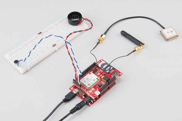
Before proceeding with this example, you'll need to connect a microphone and speaker to your shield. You'll also need to make sure your cell plan includes the ability to make and receive voice calls.
If you're using a passive microphone and speaker, you can simply connect them to the differential pins on the audio port. Connect the microphone pins to MIC+ and MIC- and speaker wires to SPK+ and SPK-. Or you can come up with a more elegant, amplified solution using the single ended inputs.
It is important to remember which pair of audio channels you use, the MG2639 can only interact with one at a time.
Running the Example
To load up the MG2639_Phone example, go to File > Examples > SparkFun MG2639 CellShield > MG2639_Phone.
Depending on which audio channel you use, you may need to alter the phone.setAudioChannel(AUDIO_CHANNEL_DIFFERENTIAL) line to phone.setAudioChannel(AUDIO_CHANNEL_SINGLE). Then click upload.
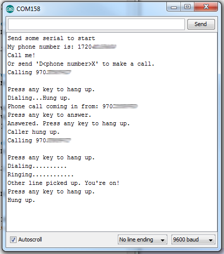
As with every other sketch, send any character in the serial monitor to make it run. Next, either try calling your MG2639 from another phone, or type D1234567890X to dial a phone number ("D" indicates the beginning of a phone number, "X" indicates the end, they're case-sensitive).
If a call is coming in, the serial terminal will print a message saying so. Press any key to answer it. While the call is active, press any key to hang up.
Using the Library: Phone
Once again, to segment out the library, a separate class is defined for phone functions: phone. Here is a quick rundown of functions made available:
Incoming/Outgoing Phone Call Status
You can use phone.status() to check whether the phone is ringing, dialing, active or idle. This function will return one of the following constants:
- CALL_ACTIVE -- Active phone call. Either an outgoing call has been picked up or an incoming call was
phone.answer()'ed and hasn't been hung up yet. - CALL_DIALING -- An outgoing call is in the process of dialing. This status precedes ringing.
- CALL_DIALED_RINGING -- An outgoing call has been dialed and is ringing on the other end.
- CALL_INCOMING -- A call is coming in. If a speaker is attached it should be ringing.
Check out the comments in the example sketch for help using this function.
Caller ID
If a call is coming in, you can use the callerID(char * phoneNumber) function to attempt to get the number. This function only returns an error code, it requires a character array be passed to it by reference so it can store the calling number there.
Here's a simple function from the example that gets the caller ID and prints it to the serial monitor:
language:c
void printCallerID()
{
  char yourPhone[15];
  phone.callerID(yourPhone);
  Serial.print("Phone call coming in from: ");
  Serial.println(yourPhone);
  Serial.println("Press any key to answer.");
}
Answering, Rejecting, and Hanging Up
If a call is coming in -- phone.status() is returning CALL_INCOMING -- you can use phone.answer() to pick it up.
If you've checked the caller ID and don't really feel like talking to the individual paired with that number, you have two options: ignore the call until they hang up or run phone.hangUp() to reject the call.
Likewise, if you've answered the call and want to end it, call phone.hangUp() to close the line.
Dialing
If you want to initiate a phone call, use phone.dial(char * phoneNumber) to start dialing. phoneNumber should be a character array formatted like any phone number you would dial from a normal phone. If you're in the same area code, it may be as few as 7 digits (assuming it's a U.S. number). On the other end of the spectrum, with international codes included, the number can be as long as 15 digits.
Here's a quick example:
language:c
char destinationPhone[] = "13032840979"; // SparkFun HQ - 1-303-284-0979
phone.dial(destinationPhone); // Dial the phone number
Serial.println("Dialing");
do
{
    int phoneStatus = phone.status();
    Serial.print(".");
} while ((phoneStatus != CALL_ACTIVE) || (phoneStatus != CALL_IDLE))
if (callStatus == CALL_ACTIVE)
    Serial.println("Other end picked up!");
Again, you can use phone.hangUp() to end the call, unless the other party does so first.
Example Bonus: Posting to Phant
The motivating factor behind us seeking out a solid cellular module was finding a reliable tool to remotely post environment data to our data service running Phant. We'd be remiss if we didn't show at least one example of how to use the hardware and IoT service together.
Download the Phant Library
A sketch included with the library -- MG2639_Phant -- requires an additional library to take care of Phant posts. Download the library from our Phant-Arduino repo, or by clicking the button below:
Again, follow the Installing an Arduino Library tutorial for help installing it.
Running the Example
Open the MG2639_Phant example sketch by going to File > Examples > SparkFun MG2639 CellShield > MG2639_Phant.
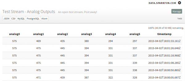
This sketch is set up to use a pre-defined stream -- DJjNowwjgxFR9ogvr45Q. Feel free to use that for testing, but don't abuse it or rely on it too much (it's very possible our powers combined will exceed the post limit). This example gathers the Arduino's analog pin values and posts all six of them to the stream.
To run the sketch, open the serial monitor and send any character to start a post.
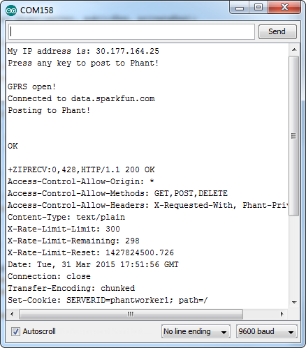
Any response from the HTTP server will be routed back out to the serial monitor. Look for "HTTP/1.1 200 OK" to verify that the post was successful. You should also see an updated set of numbers on the stream page.
As the sketch continues to run, you can send another character over serial to initiate a new post. Just take care to only send one character at a time -- and don't abuse the strem!
Memory Limitations
The MG2639 library can really test the limits of the Arduino's memory. You'll notice that in most of these examples we put large, constant strings in flash (e.g. Serial.println(F("Hello, world"));). In this example we're also storing the Phant field strings in flash.
You'll notice that most of these examples sacrifice flash storage space for as much SRAM as we can get. If your sketch mysteriously resets, or isn't working as you'd expect, you may be running out of memory. It can be a diabolically hard problem to diagnose and fix, but start with trying to eliminate big strings and large arrays.
Resources and Going Further
We hope you'll enjoy creating with the MG2639 Cellular Shield. If you have any questions about the board itself, these resources may be helpful:
For information about using the MG2639's GPS module, check out our GPS Basics and GPS Shield tutorials. We highly recommend using the Tiny GPS library for all of your GPS-string-parsing-in-Arduino needs.
If you'd like to continue exploring the tutorials in our catalog, here are a few related guides we'd recommend:
Serial Graphic LCD Hookup
Graphic LCD Hookup Guide
Whether you want to connect an LCD to your shield to make a fully navigable cell phone, or want to log sensor data to data.sparkfun.com, the MG2639 Cellular Shield should serve as a solid launching point.
