Retired - Electric Imp Breakout Hookup Guide
This Tutorial is Retired!
An electric imp hug! Provides an overview of the imp card and breakout. Both hardware and firmware subjects are covered.
View the updated tutorial: Retired - Electric Imp Breakout Hookup Guide v2
 jimblom
About the Breakout
In order to use an electric imp, two pieces of hardware are required: the imp card and the impee. An impee is the piece of hardware that houses the imp. Aside from having a standard SD socket for the imp to slide into, the impee also needs to provide power to the imp, and do something with the imp's I/O pins. Our impee for this tutorial is as simple as it gets...a breakout board.
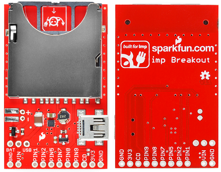
The imp breakout provides the bare minimum you should need to add an electric imp to your project. There's an SD socket, a step-down voltage regulator, and every I/O pin of the imp is broken out to a 0.1"-spaced header.
Powering the Breakout
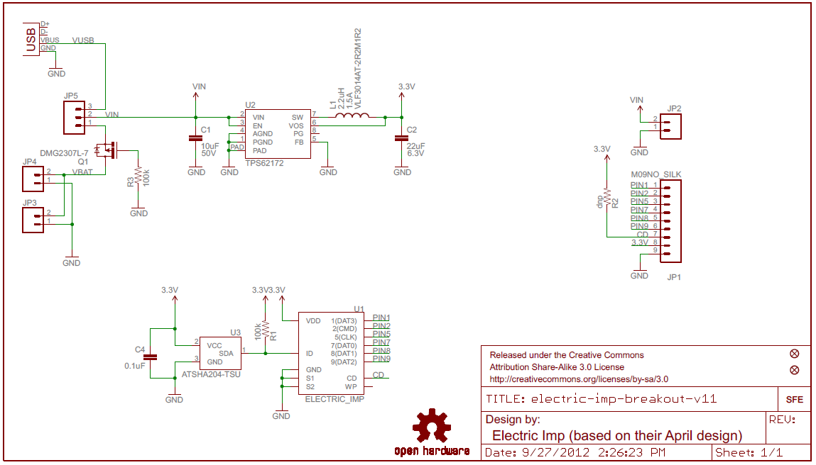
A big chunk of the circuitry on the Breakout board is a 3.3V TPS62172 step-down regulator (and the inductor/capacitors supporting it). This regulator allows for input voltages anywhere between 3.3V and 17V (voltages in the upper end of that range may produce some heat). It can support up to 500mA of continuous current.
There are three power inputs on the board, all of which, are fed into the on-board 3.3V regulator:
- "VIN" header - This standard 0.1" header feeds directly into the 3.3V regulator.
- Battery input - These are the pins and pads labeled "+" and "-". The footprint of the two through-hole pins matches up to a PTH 2-pin JST connector, which mates with our LiPo batteries (or AA batteries). This input needs to be selected using the jumper (see below).
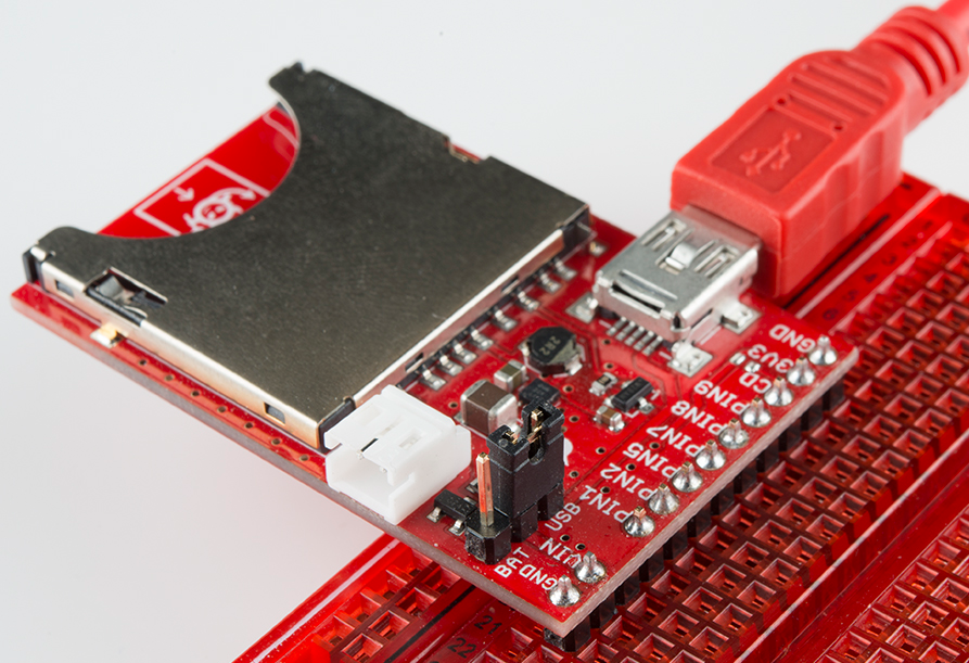
- USB mini-B connector - This power input should feed a clean, 5V source into the breakout board's regulator. The USB voltage supply can come from either a mini-B cable connected to your computer or a USB wall adapter. This input needs to be selected using the jumper (see below).
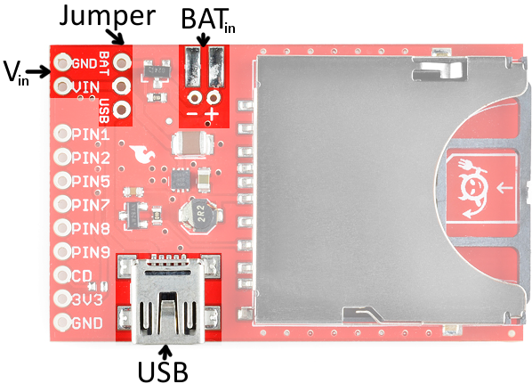
Setting the Jumper
To use either the battery or USB power inputs, a jumper must be set on the board. To use the jumper, first solder a 3-pin male header to the jumper pins. Then use a 2-pin jumper to span from the middle pin, to whichever of the two inputs you'd like to use.
The Breakout's Schematic
There are three main components to the breakout board: a TPS62172 step-down regulator (U2), the electric imp socket (U1), and the ATSHA204 authentication chip (U3).
Pinout
All of the imp's GPIO pins are broken out to the 0.1"-spaced header, along with a few related power pins:
- GND - Common pin for input voltage.
- VIN - Input voltage supply fed into regulator.
- PIN1 - imp pin 1 (DAC, UART1289 CTS, UART12 TX, I2C12 SCL, SPI189 SCLK)
- PIN2 - imp pin 2 (UART1289 RTS, UART12 RX, I2C12 SDA, SPI257 MISO)
- PIN5 - imp pin 5 (DAC, UART57 TX, SPI257 SCLK)
- PIN7 - imp pin 7 (UART57 RX, SPI257 MOSI)
- PIN8 - imp pin 8 (UART1289 TX, I2C89 SCL, SPI189 MOSI)
- PIN9 - imp pin 9 (UART1289 RX, I2C89 SDA, SPI189 MISO)
- CD - Card detect. This signal will connect to GND whenever a card is inserted into the socket.
- 3V3 - 3.3V output from regulator.
- GND - Common ground.
ID Chip
There's actually one more piece of hardware required of the impee: an ID chip, which provides each impee with a unique identification code. This means that every impee you encounter should include an Atmel ATSHA204 authentication chip. The imp automatically interfaces with this chip every time it boots up, so it can identify which impee it's plugged into. This actually turns out to be pretty awesome, because the program that an imp runs depends on what impee it's plugged into. If you had two impees in your house -- say controlling an irrigation system and another controlling a coffee machine -- one, single imp would run two different programs depending on which machine it was plugged into.
You shouldn't ever have to fuss with the ID chip. In fact, you can forget we ever said anything about the ATSHA204!