Retired - Electric Imp Breakout Hookup Guide v2
This Tutorial is Retired!
This tutorial covers concepts or technologies that are no longer current. It's still here for you to read and enjoy, but may not be as useful as our newest tutorials.
 jimblom
Example 1: I/O Control
The electric imp can do most anything an Arduino or similar microcontroller can. It's got analog-to-digital converters, PWM, SPI, I2C, UARTs, and it even has digital-to-analog converters. In this snippet of example code, we'll dig further into the imp's I/O control delving into digital and analog input/output.
The Circuit
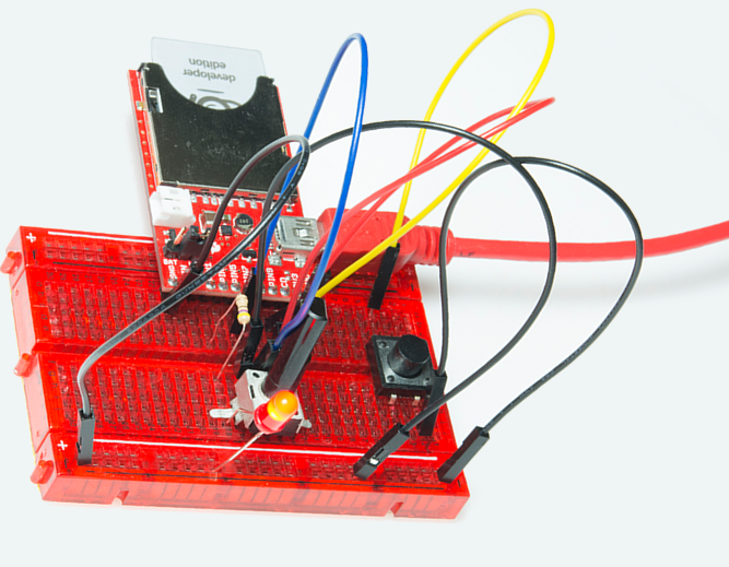
The setup for this example code requires three unique components: an LED, potentiometer, and a button (plus a current-limiting resistor for the LED). Here's a fritzing diagram and schematic (click to see it bigger) for our circuit:
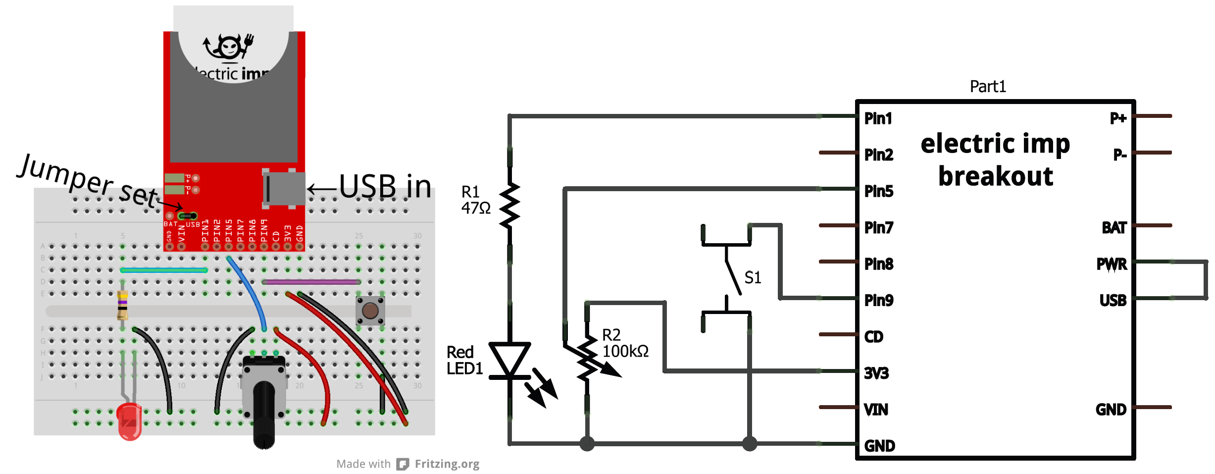
Make sure the imp is getting power. USB is usually the quickest/easiest way to apply power to the breakout board, but you'll need to set the jumper accordingly.
The IDE
To create a new piece of code, we need to create a new "model" and associate it with our Breakout Board impee. To do this, hover over your impee and click the "settings" gear. The familiar Device settings window should pop up. Under the _Associated model: box, create a new model named I/O Control. Then click Save Changes.
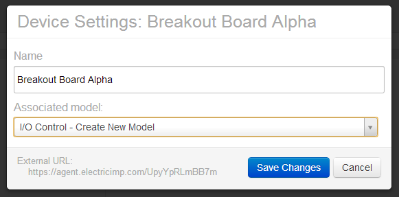
This will create a new tab on the left side labeled I/O Control. If you expand that tab, you'll see that the Breakout Board impee has be reassigned there.
The Code
Once again, we'll only be using the Device portion of the IDE. Copy and paste everything from the below box, into your Device window and click Build and Run up top.
language:Squirrel
/* Digital Input, Analog Input, PWM Output Example
   by: Jim Lindblom
   SparkFun Electronics
   date: July 15, 2013
   license: Beerware. Use, reuse, and modify this code however you see fit.
   If you find it useful, buy me a beer some day!

   This is a simple piece of code which uses an LED, potentiometer, and button.
   The LED connects to pin 1 through a 47 ohm resistor. The cathode of the LED should connect to ground.
        This means writing pin 1 will turn the LED on, and writing it to 0 turns the LED off.
   The button connects on one side to pin 9, and the other pin of the button goes to ground.
        We'll use the internal pull-up resistors on pin 9 to bias the button high.
        When the button is pressed, pin 9 should read as low.
   The wiper of the potentiometer is connected to pin 5. The other two pins of the pot should be
        connected to +3.3V and GND. This'll make the voltage at pin 5 adjustable from 0-3.3V.
*/

////////////////////////////////////////
// Function definitions               //
////////////////////////////////////////

local ledState = 1; // Says local, but think of this as a global var. Start with LED on

// function pin9Changed() will be called whenever pin 9 goes from high->low or low->high
function pin9changed()
{
    local buttonState = hardware.pin9.read(); // Read from the button pin

    if (buttonState == 0) // Button will read low if pressed
    {
        ledState = ledState ? 0 : 1;    // Flip flop ledState
        server.log("Button pressed!");
    }
    else // Otherwise button was released, no action
    {
        server.log("Button released");
    }
}

// Loop constantly updates the LED. If ledState is 1, we'll read the pot, and set the LED brightness accordingly.
// If ledState is 0, we'll just turn the LED off. ledState is updated in the pin9Changed() function.
function loop()
{
    if (ledState == 1)
    {
        local rawValue = hardware.pin5.read();  // Read from the potentiometer. Returns a value between 0 and 65535.
        rawValue /= 65535.0;  // Make rawValue a % (and a float). The pin write function requires a value between 0 and 1.
        hardware.pin1.write(rawValue);  // Pin 1 is already configured as PWM, write potentiometer value
    }
    else
    {
        hardware.pin1.write(0);  // Write pin 1 low -- LED off
    }

    // This must be called at the end. This'll call loop() again in 10ms, that way it'll actually loop!
    imp.wakeup(0.01, loop);
}

////////////////////////////////////////
// Setup Stuff: Runs first at startup //
////////////////////////////////////////
hardware.pin1.configure(PWM_OUT, 0.0005, 0.0);   // Configure Pin 1 as PWM output, 5ms period, 0% high (off)
hardware.pin5.configure(ANALOG_IN); // Configure pin 5 as analog input
hardware.pin9.configure(DIGITAL_IN_PULLUP, pin9changed); // Configure pin 9 as digital input (with pull-up enabled). On change it'll call function pin9changed().
imp.configure("LED Trigger Wiper", [], []);

loop(); // Call loop, and let the program go!
The code creates an adjustable-brightness LED controller. The brightness of the LED is adjusted by turning the potentiometer. Pressing the button will turn the LED on and off.
Explaining the Code
The skeleton of this code acts a lot like that of Hello, blink. The function definitions are up top, the setup stuff runs at the bottom, and loop() is called at the beginning. loop() continually calls itself, using the imp.wakeup(0.01, loop) function call, every 10 ms.
The loop() function again relies on an ledState variable. If ledState is 1, we read the potentiometer voltage, and adjust the brightness of our LED accordingly.
The ledState variable is flip-flopped in the pin9changed() function. This is like an interrupt. It's called whenever the state of pin 9 changes -- if it goes from high to low, or low to high. When setting up pin 9 as a digital input, we added this function as the one to be called when the state change occurred.
Check out the comments in the code for a more in-depth overview of each function call. Or, for more information, check out electric imp's API reference.
Enough hardware stuff! The next two examples will make use of the imp's greatest feature...it's web connectivity.