RedBoard Santa Trap
Contributors:
 Sarah Al-Mutlaq
Assembly
With this set up, you can try to catch Santa coming down the chimney, but even if he's clever enough to get past motion sensor without being detected, you can catch him when he goes to drink the milk left out for him.
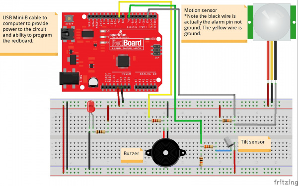
Click image for a larger view.
The circuit works as follows:
- The LED is connected from ground to 5V [1] through a resistor so it will be lit when there is power. This functions as an “ON” indicator, should the circuitry be far away from the RedBoard.
- The motion sensor has an alarm pin that goes LOW when it detects motion, so we can check that by hooking it up to the RedBoard and using a resistor to pull it to HIGH (or 5V) when it isn’t detecting motion.
- The tilt sensor acts like a closed circuit when it is upright. However, it acts like an open circuit if it is tilted past 15 degrees. This means that we can set up a circuit with two resistors and hook it up to the RedBoard so that when the tilt sensor is upright, the RedBoard pin will read HIGH (or 5V), and, when it is tilted, the RedBoard pin will read LOW (0V or Ground).
- All that is left is to hook up the buzzer, which just needs to go from ground to an output pin from the RedBoard, where the RedBoard can give it power. In this fritzing diagram, it’s set up with a resistor, but that isn’t needed unless you want the buzzer to be quieter. The bigger the resister you put in series with the buzzer, the less noise the buzzer will make.
[1] Note: The PIR motion sensor can work with at least 5V. However, the voltage may not be enough for the L78L05 voltage regulator to work reliably depending on your power supply. For more information, check out the note in the PIR Motion Sensor Hookup Guide.
