RedBoard Hookup Guide
 jimblom
Meet the RedBoard
Below is an annotated image, and a quick overview, of all of the important stuff on the RedBoard:
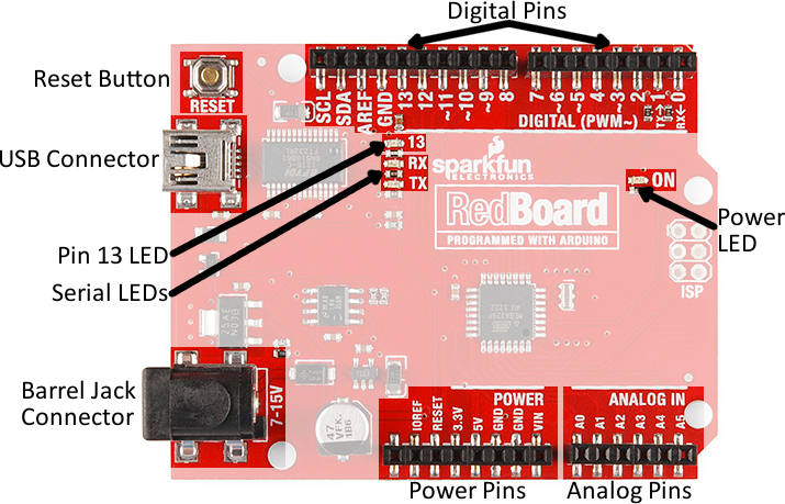
Supplying Power
The RedBoard can be powered via either the USB or barrel jack connectors. If you choose to power it via USB, the other end of the USB cable can be connected to either a computer or a (5V regulated) USB wall charger.
The power jack accepts a center-positive barrel connector with an outer diameter of 5.5mm and inner diameter of 2.1mm. Our 9V and 12V adapters are good choices if you're looking to power the RedBoard this way. Any wall adapter connected to this jack should supply a DC voltage between 7 and 15V.
USB is usually the easiest way to power the board, especially when you're programming it, because the USB interface is required for uploading code too. Why would you use the barrel jack? Usually it's because you need more power. A USB port is usually only allowed to supply 500mA, if you need more than that a wall adapter may be your only choice.
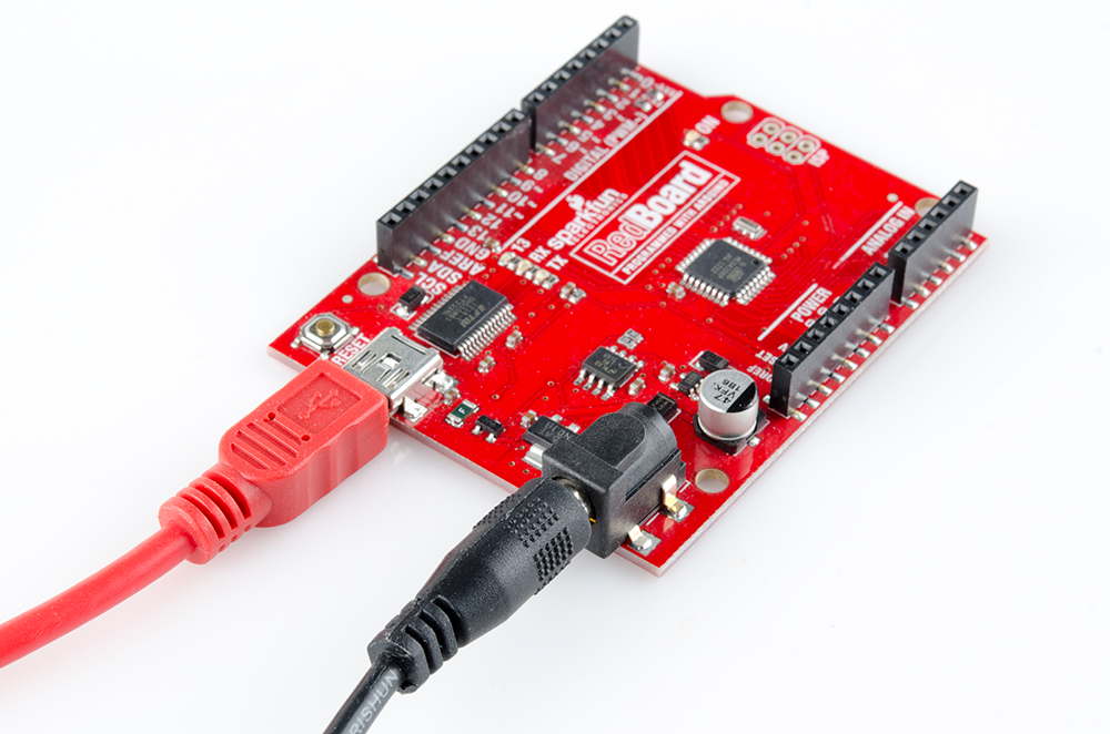
It is acceptable to connect both a barrel jack and a USB connector at the same time. The RedBoard has power-control circuitry to automatically select the best power source.
Using the RedBoard Headers
All of the RedBoard's pins are broken out to 0.1"-spaced female headers (i.e. connectors) on the outer edges of the board. Most pins are arranged into logical collections -- there are headers dedicated to power inputs/outputs, analog inputs, and digital inputs.
The digital pins are the digital inputs and outputs of the Arduino. These are what you connect to buttons, LEDs, sensors, etc. to interface the Arduino with other pieces of hardware. Pins marked with a tilde (~) can also serve as analog outputs, which you can use to dim LEDs or run servo motors.
There are six analog inputs on the analog header. These pins all have analog-to-digital converters, which can be used to read in an analog voltage between 0 and 5V. These are useful if you need to read the output of a potentiometer or other analog sensors. All six analog pins can also serve as digital inputs and outputs.
The power header is mostly full of voltage supply pins. These pins are traditionally used as power sources for other pieces of hardware (like LEDs, potentiometers, and other circuits). The '3.3V' and '5V' pins are regulated 3.3V and 5V voltage sources. The 'GND' pins are the common ground -- the 0V reference for those voltage supplies. 'VIN' is the input voltage, it'll be equal to the voltage of your input supply if you have a wall adapter connected. If nothing is connected to the barrel jack, and you're powering the board via USB, VIN should be around 5V.
Connecting to the Headers
There are a variety of wires, connectors, and other items that can be inserted into these headers to interface with the Arduino. Jumper wires are a good option, if you want to connect the RedBoard up to other pieces of circuitry that may live on a breadboard.

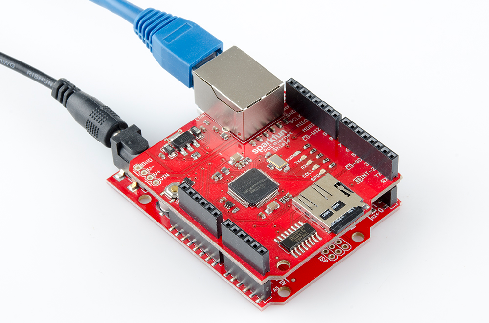
Arduino shields are another popular way to interface with the RedBoard connectors. These Arduino-shaped boards piggyback onto the RedBoard, and connect to all four headers at once. Shields exist in hundreds of forms, they can add GPS, WiFi, MP3 decoding, and all sorts of other functionality to your Arduino.
And there are plenty of other interfacing options too. If you have a 0.1"-spaced connector, like a Molex, you can plug that right in. Or just strip and cut some wire.