Red Hat Co.Lab Light Sensing Kit Experiment Guide
 D___Run___, Member #803053
Part 1: Breadboard and Light Sensing
What is a circuit?
A circuit is a closed loop that electricity can travel around that, at its most basic, consists of three parts:
- a voltage source: the power for the circuit
- a load: the thing that is being powered, like a motor, buzzer, or light
- the circuit path: the continuous path that the current follows as it travels around the circuit
An example of a simple circuit would be a power source (like a battery), a load (like a light), and the circuit path (the wires that connect them).
The Power/Voltage Source
Your kit comes with either four AA batteries and a battery holder, or a 9v battery and 9V snap connector. This is the power/voltage source.
Either the battery pack or the snap connector will have a plastic connector—the small, white, rectangular box at the end of the red and black wires. This makes it easy to connect to many types of electronics; however, wewill be using be using it in a different way for our project today. The way we will connect the power to the breadboard is actually with jumper wires. Jumper wires are short in length and make connecting components quick and easy.
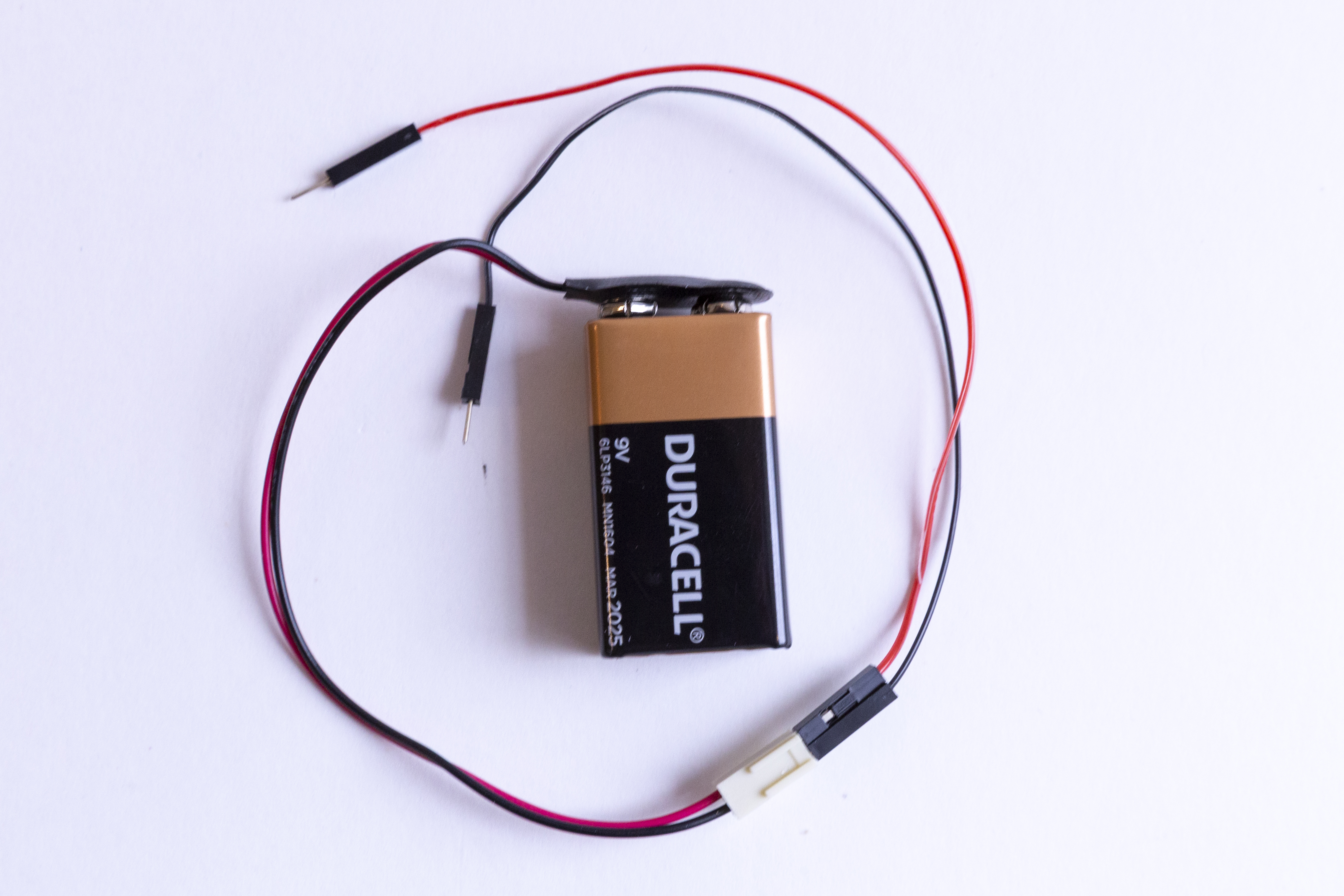
The jumper wires that come in your kit have small metal pins on either side. The colors of the jumper wires don’t correspond to anything in your kit. Use any two colors that you prefer.
The Load
For this circuit, we want to use a photocell to trigger a motor.
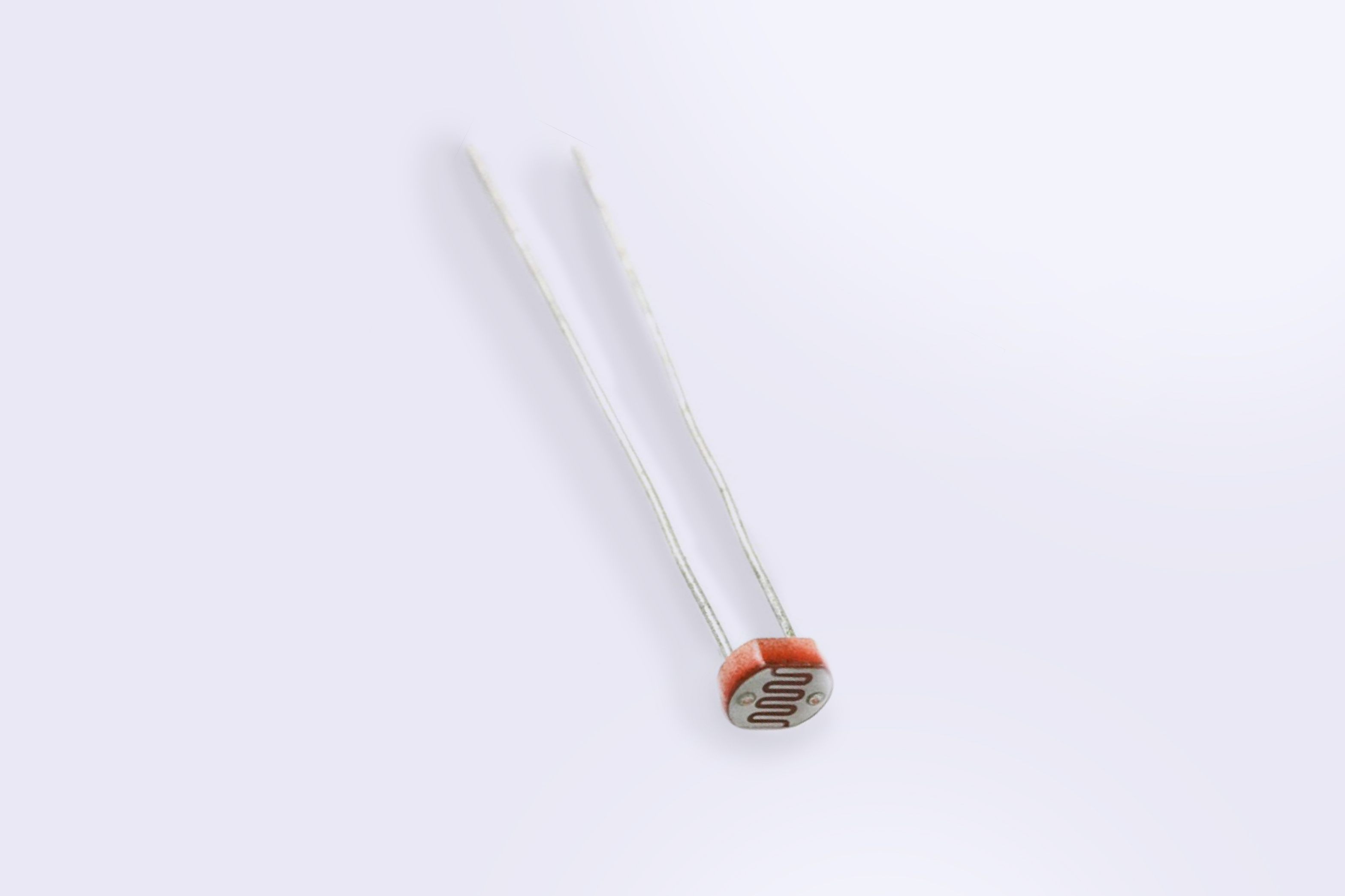
A photocell will resist the flow of the power until enough light is sensed. It will then “open” or allow the signal to pass through. So, a photocell is a light sensor—it senses light, and the amount of brightness causes another piece of our kit to function. We can think of it as a gate that we have to open in order to continue down the (circuit) path. Once the signal passes through the photocell, it can reach our motor. When the motor receives power, it will spin.
Before we use the motor, we want to make it work like a fan. This means we want to attach a small propeller to the part that spins. Using the box your kit came in, cut out a propeller of your own design—it can be short or long, rectangle or oval. After you have it cut out, use your scissors to poke a small hole in the center just big enough to gently push onto the white gear at the end of the motor (the part that spins).
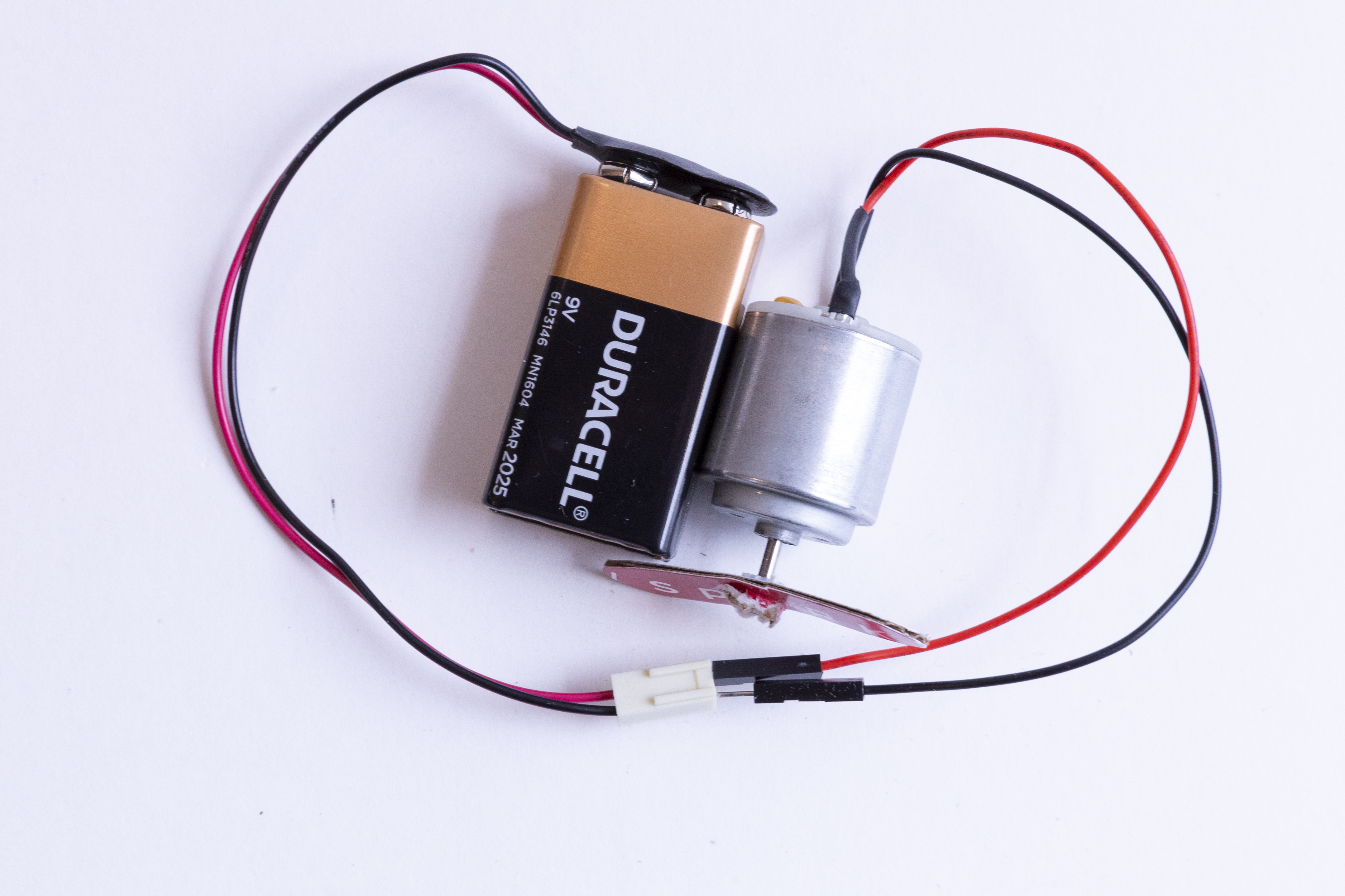
Now let's see how the motor works when we don’t interrupt the signal with the photocell. Your kit includes wires that have pins on either end of them. We call these jumper wires. Take the jumper wire ends from the battery pack and hold them directly against the ends of the motor connections. You’ll see the motor jump a bit at first as the power flows into it and the white cap at the end start to spin. I wonder what happens if we reverse which motor wires touch the battery jumper wires…
The Circuit Path
For a circuit to work, the path of the power can’t be interrupted—all pieces have to be in contact. Luckily, we have a breadboard which is a helpful tool that we can use to quickly plug in items and keep them connected. It also lets us create, fix small mistakes, and practice with the components.
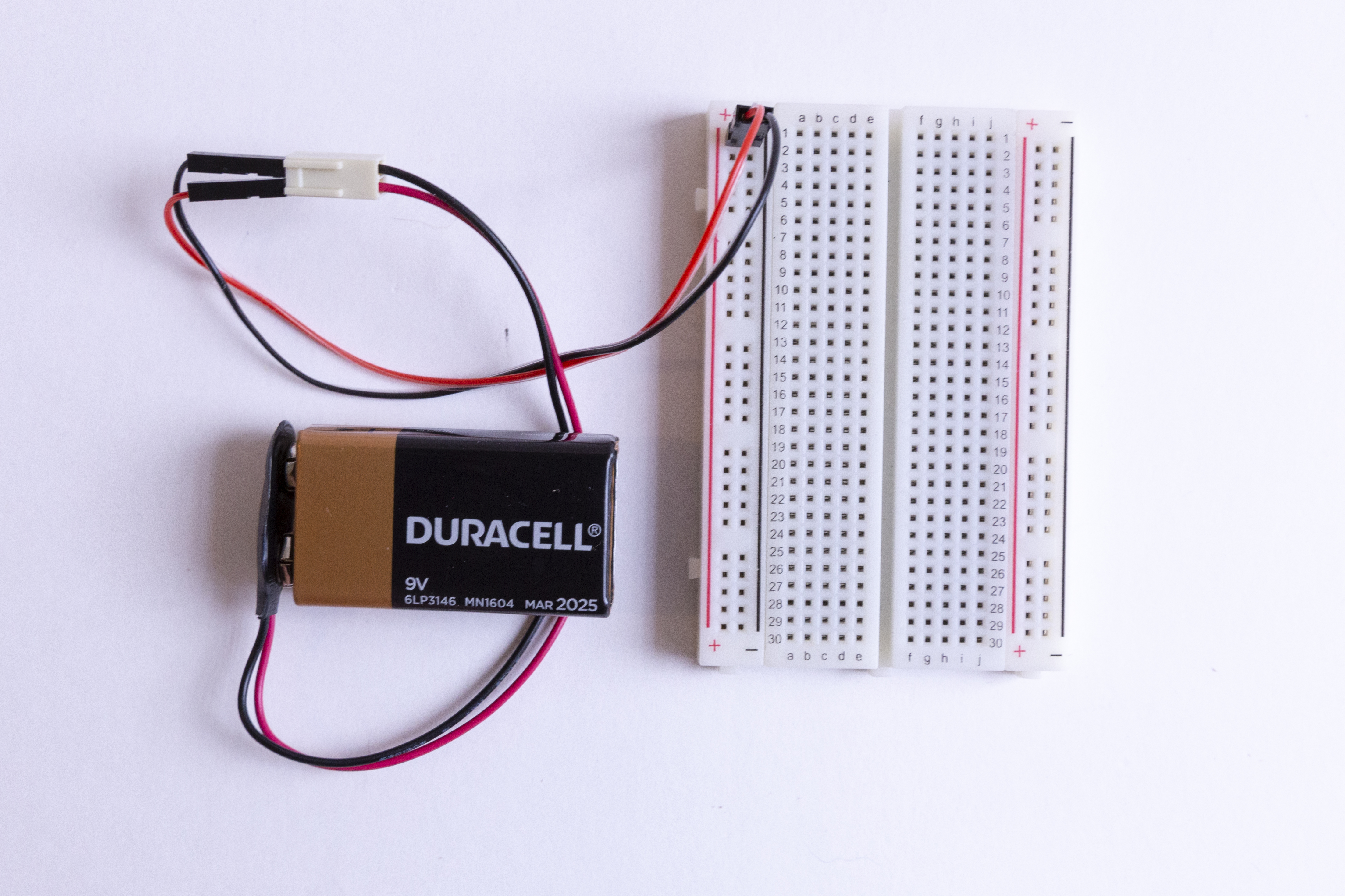
Let’s start by taking a look at the breadboard that is included in your kit: First, notice that there are two long columns of holes running down each side of the board, one with a red line beside it, and one with a black line. These are called the power rails and all of the holes in a single power rail are connected to each other. If power is connected to one hole in the column, it's connected to all the other holes in the column.
There are two holes in the plastic molding at the end of the wires coming from the battery pack. Insert a jumper wire into each of these holes and insert the other ends into the (+) power rail and the (-) power rail.
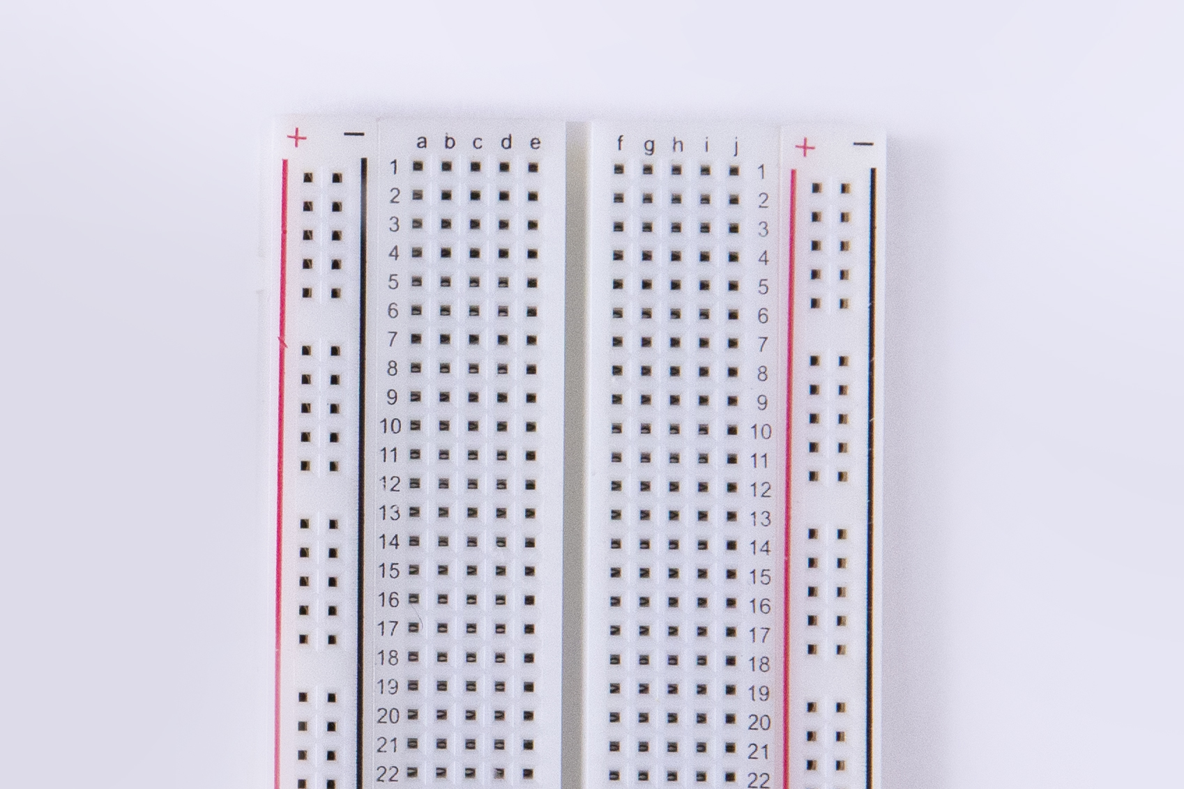
Second, all the holes in a numbered row are connected to each other, but this connection is broken at the small trench or indent that runs down the center of the board. Each side COULD be its own separate circuit. Our project will jump over the trench using jumper wires and send power back and forth! Basically, you can view a breadboard as a series of columns (labeled A-E and F-J) and rows labeled 1-30. And remember, the divide in the middle means that A5 isn’t connected to F5. When we get to the instructions down below, we will use this row and column system to mark where connections should be made (A6, E3, H23, etc.).
Catch a Breeze!
We are going to replicate this circuit (the steps are below)
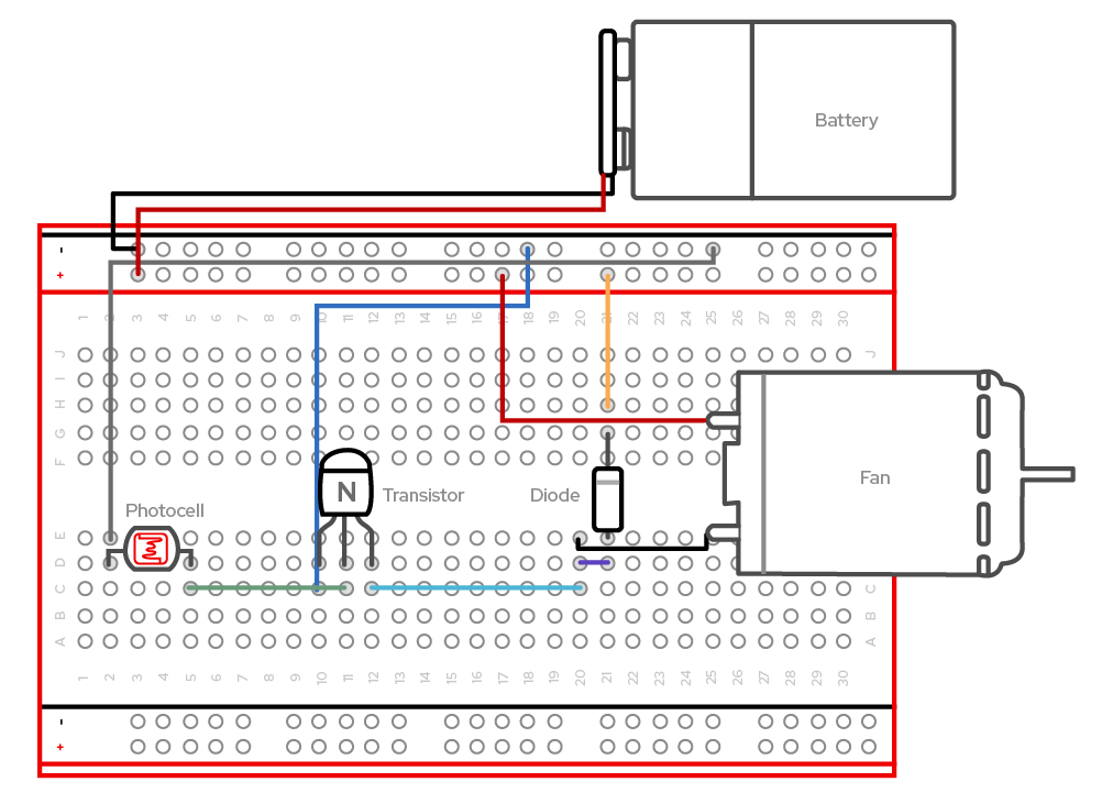
Create your circuit as follows:
- Connect a jumper wire from E2 to opposing (+) power rail 19
- Connect the photocell pins to D2 and D5
- Connect a jumper wire from C5 to C11
- Connect a jumper wire from C10 to opposing (-) power rail 14
- Connect a jumper wire from C12 to C20
- Holding the transistor with the flat side facing towards the jumper wires in C10-12, insert the 3-pin transistor into D10, D11, and D12
- Connect a jumper wire from D20 to D21
- Place the grey strip side of the diode into G21 and the other side into E21
- Connect a jumper wire from H21 to the positive (+) power rail 20
- Connect the black wire of the motor into E20
- Connect the red wire of the motor to the positive (+) power rail 17
- Connect the jumper wire attached to the positive part of the battery pack terminal to the positive (+) power rail 1 on the right.
- Connect the jumper wire attached to the negative part of the battery pack terminal to the negative (-) power rail 1 on the left.