Red Hat Co.Lab Light Sensing Kit Experiment Guide
 D___Run___, Member #803053
Introduction
In this kit you’ll find everything you need to understand the basics of a light-sensing motor.
The Red Hat Co.Lab Light Sensing kit will help you:
Learn how breadboards work through experimenting with simple circuits using a photocell and motor.
Explore how to track changes in light using a sensor, and see how these changes can affect the speed of a motor.
After you’ve built your light-sensing motor, check out the Red Hat Open Source Stories film, The Science of Collective Discovery, to see how citizen scientists are ensuring a better environment for their local communities by exploring air quality and water flow with everyday objects.
Before You Start
Before you start assembling your kit, there are some things you can do ahead of time to ensure your project will be a success. The information below will tell you how much time you can expect to spend on each part, what tools and materials you'll need, and what you can do before you start your project that will make it easier.
Recommended Age and Prerequisite Skills
This activity is best suited for ages 10-13. There are no specific skills required to complete the project, and no prior knowledge of circuits is assumed. Because some of the components are small and making connections requires a bit of dexterity, younger students may need adult assistance.
Time Requirements
Part One: Breadboarding and Light Sensing - 30 minutes
Part Two: Exploring Your Environment and Mapping Data - 45 minutes
Tools and Materials
The Red Hat Co.Lab Light Sensing kit. Make sure you keep the box it comes in. We’ll use it later.
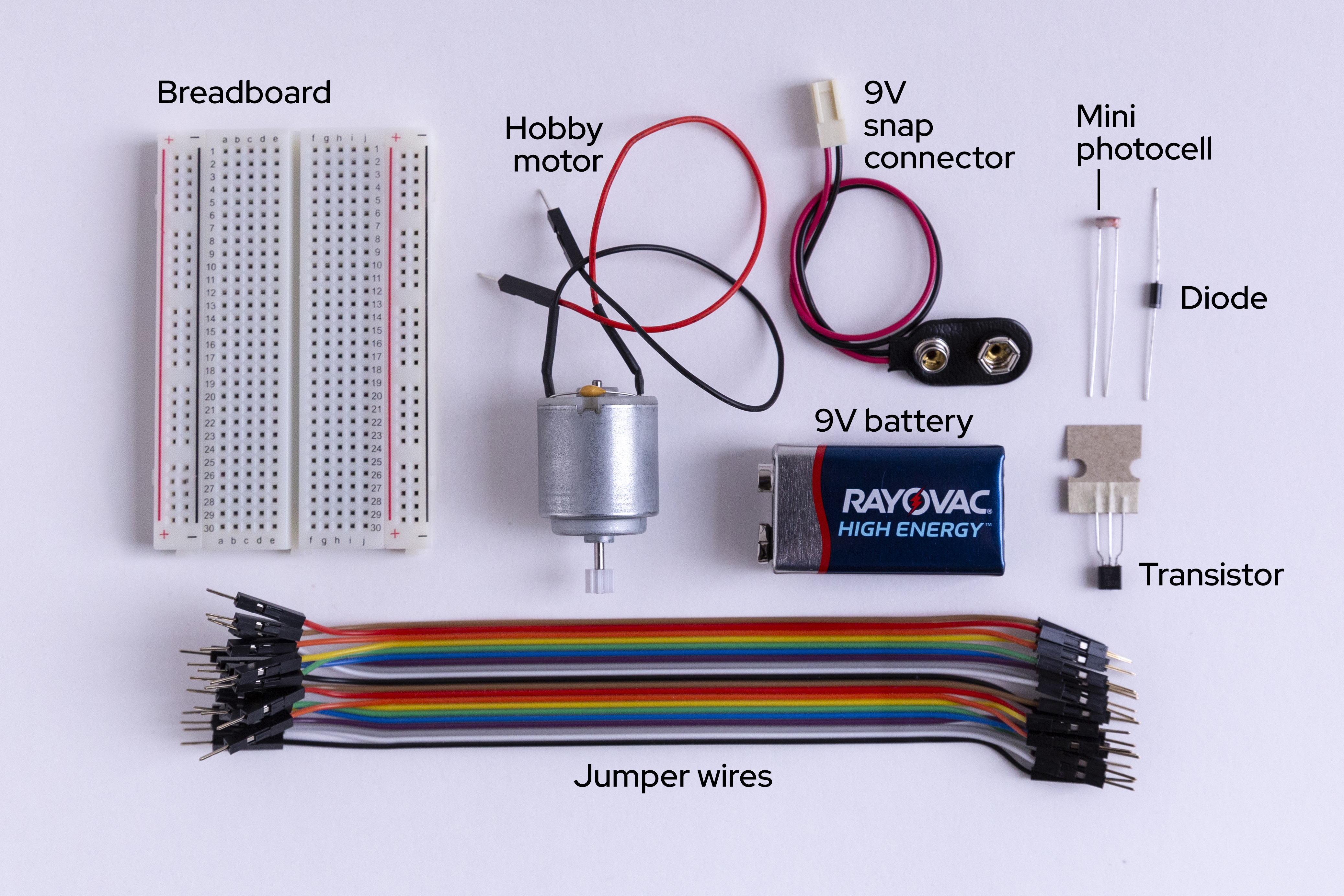
- Mini photocell
- Transistor
- Diode
- 9V battery
- 9V snap connector
- Jumper wires
- Breadboard
- Hobby motor
- Paper: for organizing and taking notes
- Scissors: for modifying the case for your experiment (cutting cardboard and paper)
- A bright location and a darker location (they can be in the same room)
Identify the Parts
It’s always helpful to know the parts you’ll be using before diving into the build. Go ahead and lay them out in front of you on a piece of paper. As you lay them out, pick them up and explore them. How many pins does a piece have? What colors are on it? Do you have a guess as to what it does based on how it looks or what it's called? You should write these observations down next to each part. It will help to organize the pieces and also your thoughts as we begin to explore and build.
And while you are laying out the parts for your project, it also helps to make sure that you have the other required materials that didn’t come with your kit (scissors). By this point we have:
- Identified each part (and labeled it so it’s easier to find)
- Counted each part to make sure that we have the correct number
- Examined each part to make sure it's not obviously broken
Now that we have taken care of the setup, we can start to build and experiment!
Resources
Below, you’ll find in-depth explorations of parts in this kit.
- Circuits: the basics of how circuits work, as well as links to more in-depth information
- Transistors: what are they, and why do you need them?
- Breadboards: a deeper dive into the interior mechanics of the breadboard
- Photocell: explore how a photocell works and senses light
Part 1: Breadboard and Light Sensing
What is a circuit?
A circuit is a closed loop that electricity can travel around that, at its most basic, consists of three parts:
- a voltage source: the power for the circuit
- a load: the thing that is being powered, like a motor, buzzer, or light
- the circuit path: the continuous path that the current follows as it travels around the circuit
An example of a simple circuit would be a power source (like a battery), a load (like a light), and the circuit path (the wires that connect them).
The Power/Voltage Source
Your kit comes with either four AA batteries and a battery holder, or a 9v battery and 9V snap connector. This is the power/voltage source.
Either the battery pack or the snap connector will have a plastic connector—the small, white, rectangular box at the end of the red and black wires. This makes it easy to connect to many types of electronics; however, wewill be using be using it in a different way for our project today. The way we will connect the power to the breadboard is actually with jumper wires. Jumper wires are short in length and make connecting components quick and easy.
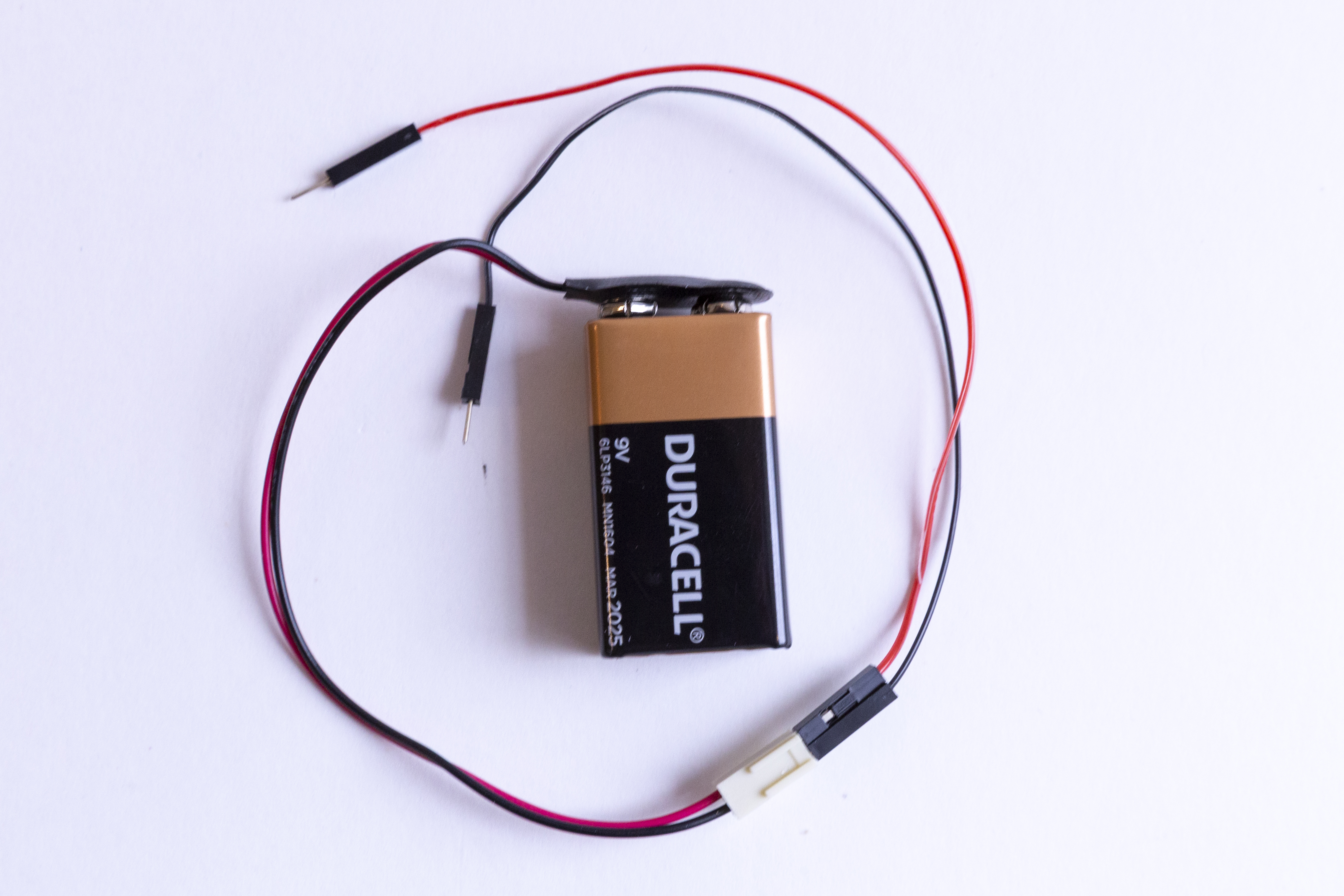
The jumper wires that come in your kit have small metal pins on either side. The colors of the jumper wires don’t correspond to anything in your kit. Use any two colors that you prefer.
The Load
For this circuit, we want to use a photocell to trigger a motor.
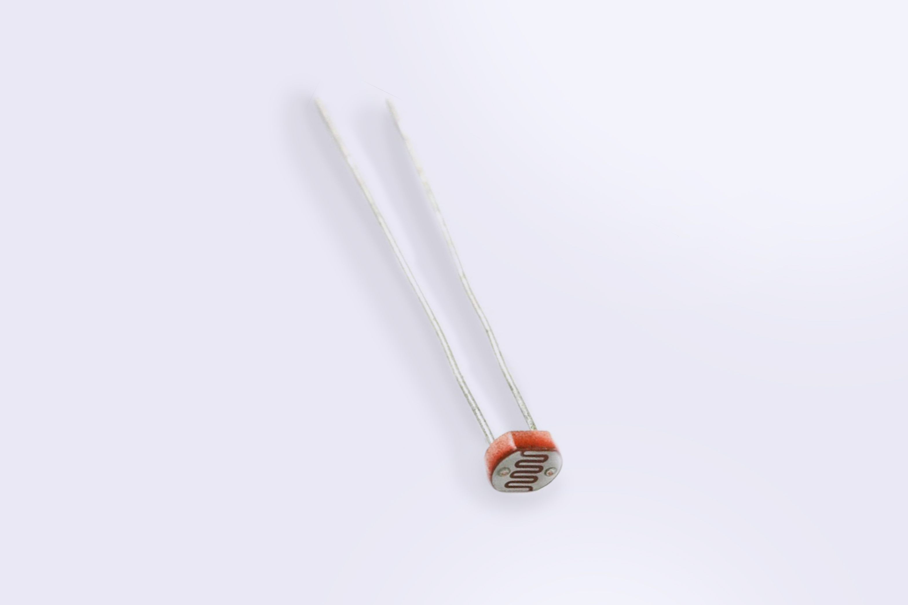
A photocell will resist the flow of the power until enough light is sensed. It will then “open” or allow the signal to pass through. So, a photocell is a light sensor—it senses light, and the amount of brightness causes another piece of our kit to function. We can think of it as a gate that we have to open in order to continue down the (circuit) path. Once the signal passes through the photocell, it can reach our motor. When the motor receives power, it will spin.
Before we use the motor, we want to make it work like a fan. This means we want to attach a small propeller to the part that spins. Using the box your kit came in, cut out a propeller of your own design—it can be short or long, rectangle or oval. After you have it cut out, use your scissors to poke a small hole in the center just big enough to gently push onto the white gear at the end of the motor (the part that spins).
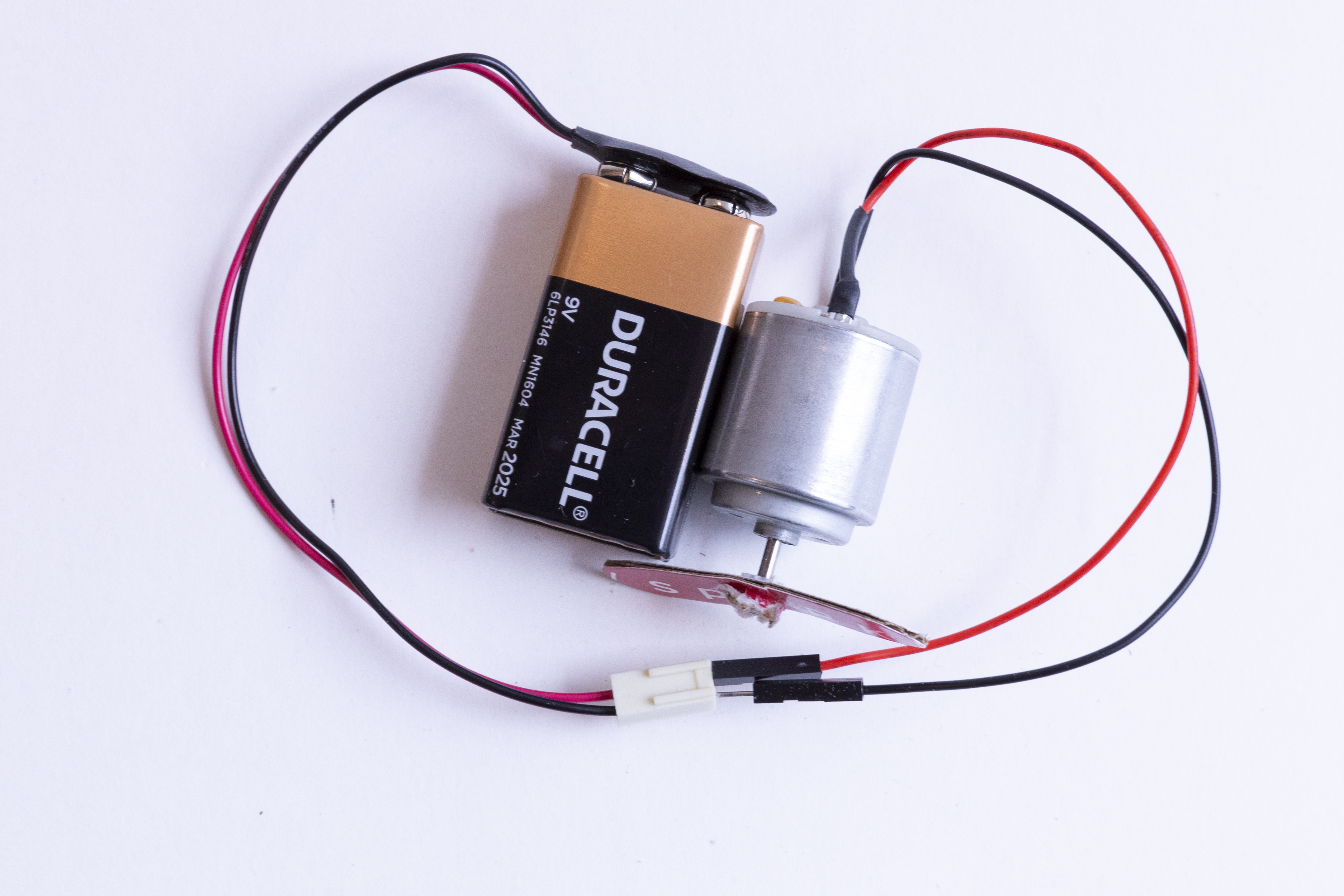
Now let's see how the motor works when we don’t interrupt the signal with the photocell. Your kit includes wires that have pins on either end of them. We call these jumper wires. Take the jumper wire ends from the battery pack and hold them directly against the ends of the motor connections. You’ll see the motor jump a bit at first as the power flows into it and the white cap at the end start to spin. I wonder what happens if we reverse which motor wires touch the battery jumper wires…
The Circuit Path
For a circuit to work, the path of the power can’t be interrupted—all pieces have to be in contact. Luckily, we have a breadboard which is a helpful tool that we can use to quickly plug in items and keep them connected. It also lets us create, fix small mistakes, and practice with the components.
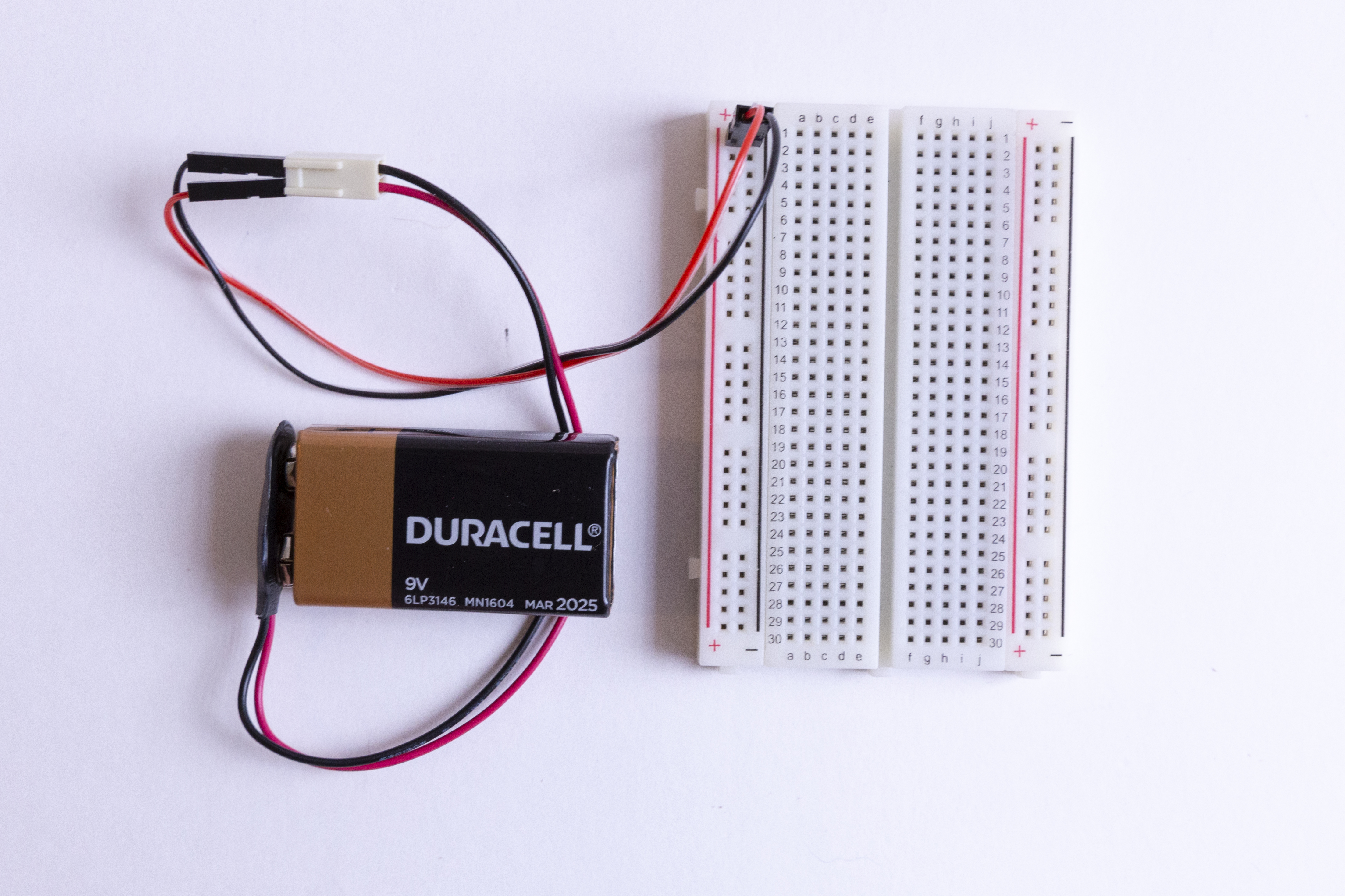
Let’s start by taking a look at the breadboard that is included in your kit: First, notice that there are two long columns of holes running down each side of the board, one with a red line beside it, and one with a black line. These are called the power rails and all of the holes in a single power rail are connected to each other. If power is connected to one hole in the column, it's connected to all the other holes in the column.
There are two holes in the plastic molding at the end of the wires coming from the battery pack. Insert a jumper wire into each of these holes and insert the other ends into the (+) power rail and the (-) power rail.
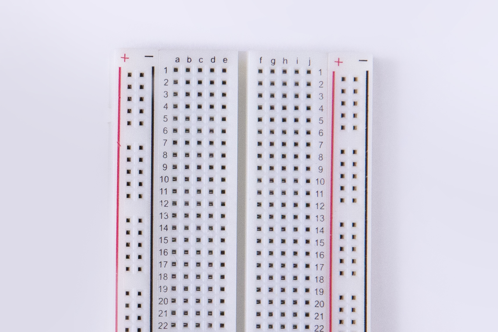
Second, all the holes in a numbered row are connected to each other, but this connection is broken at the small trench or indent that runs down the center of the board. Each side COULD be its own separate circuit. Our project will jump over the trench using jumper wires and send power back and forth! Basically, you can view a breadboard as a series of columns (labeled A-E and F-J) and rows labeled 1-30. And remember, the divide in the middle means that A5 isn’t connected to F5. When we get to the instructions down below, we will use this row and column system to mark where connections should be made (A6, E3, H23, etc.).
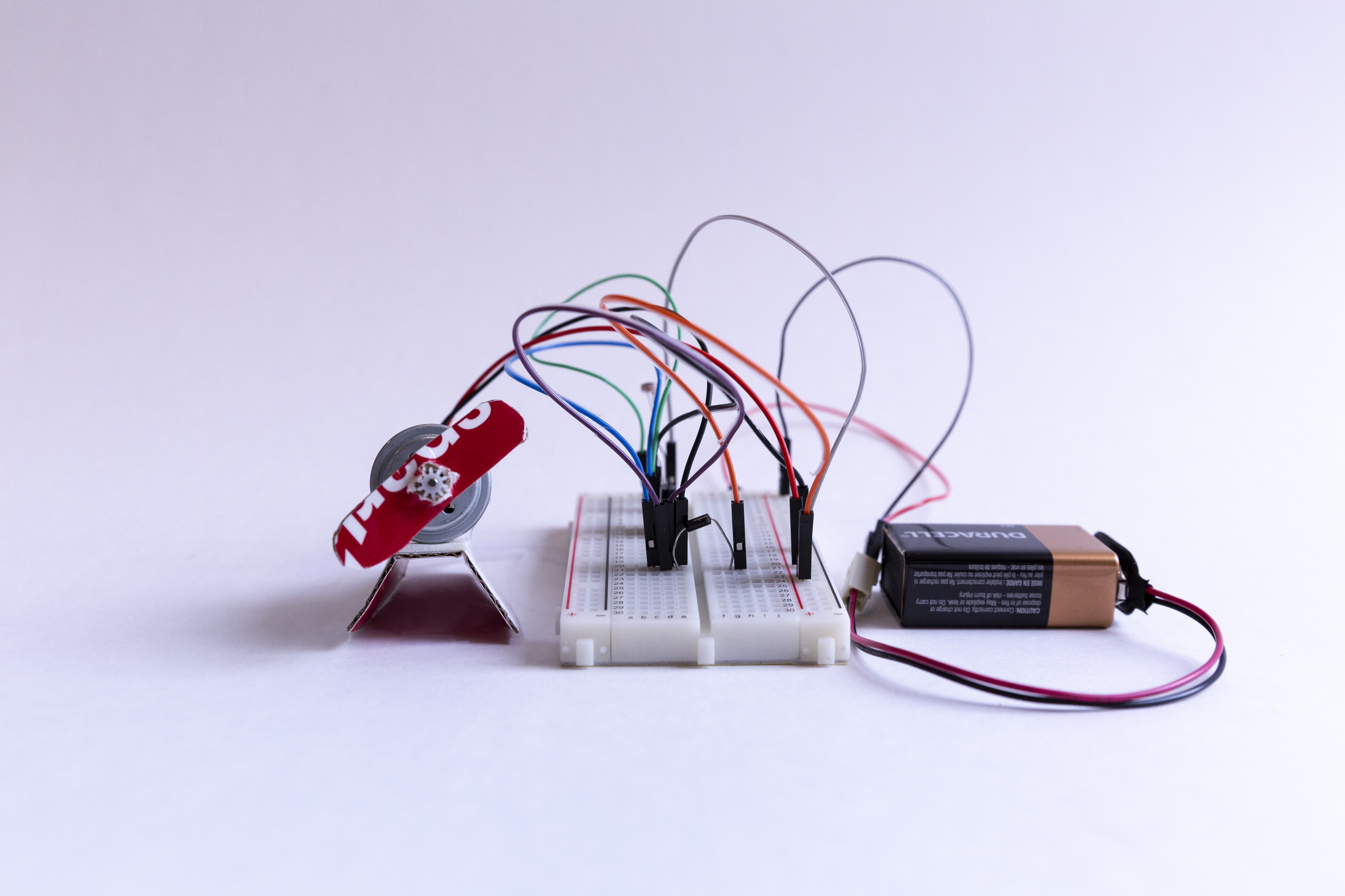
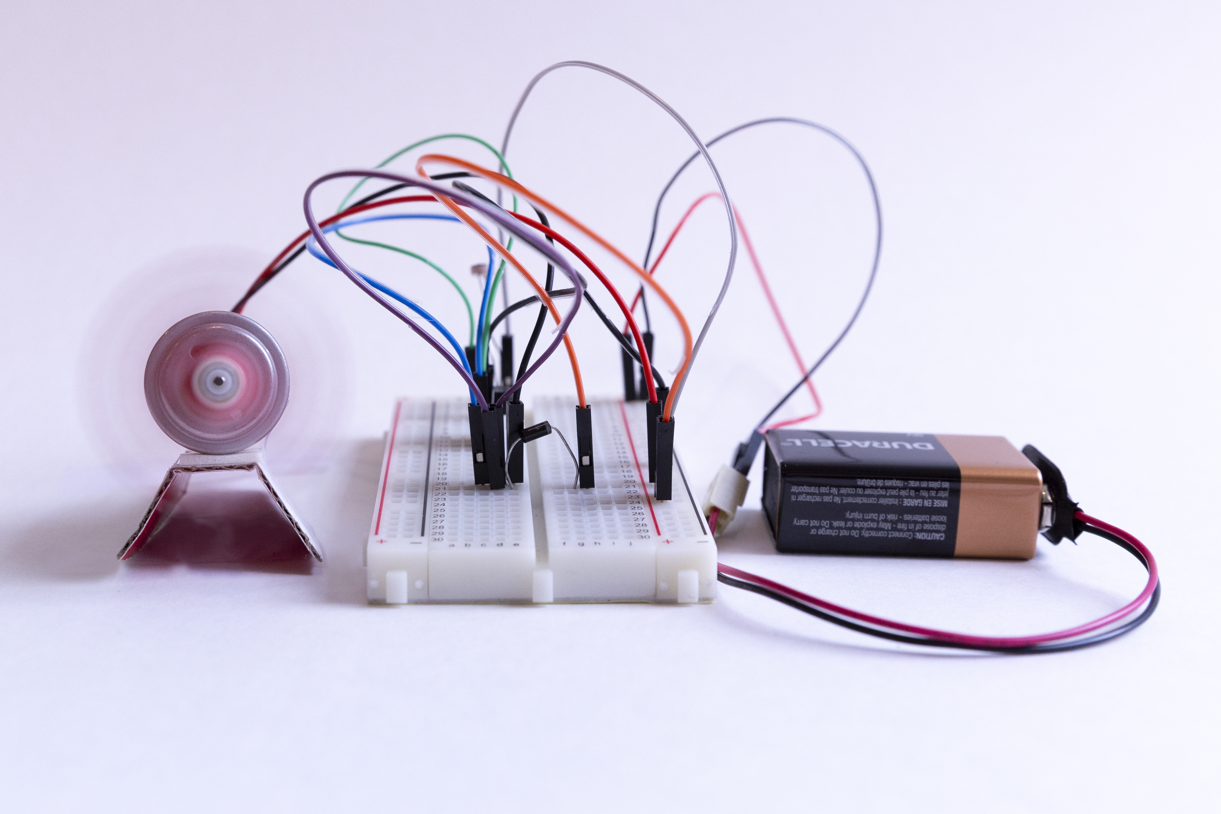
Catch a Breeze!
We are going to replicate this circuit (the steps are below)
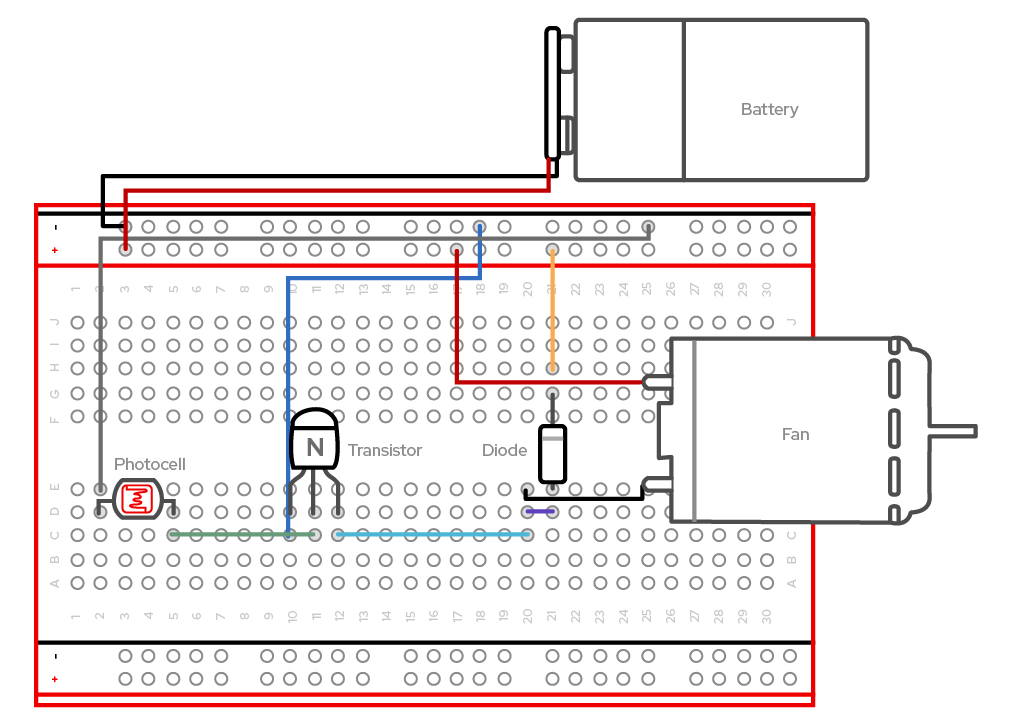
Create your circuit as follows:
- Connect a jumper wire from E2 to opposing (+) power rail 19
- Connect the photocell pins to D2 and D5
- Connect a jumper wire from C5 to C11
- Connect a jumper wire from C10 to opposing (-) power rail 14
- Connect a jumper wire from C12 to C20
- Holding the transistor with the flat side facing towards the jumper wires in C10-12, insert the 3-pin transistor into D10, D11, and D12
- Connect a jumper wire from D20 to D21
- Place the grey strip side of the diode into G21 and the other side into E21
- Connect a jumper wire from H21 to the positive (+) power rail 20
- Connect the black wire of the motor into E20
- Connect the red wire of the motor to the positive (+) power rail 17
- Connect the jumper wire attached to the positive part of the battery pack terminal to the positive (+) power rail 1 on the right.
- Connect the jumper wire attached to the negative part of the battery pack terminal to the negative (-) power rail 1 on the left.
Part 2: Exploring Your Environment
Testing
Once you complete the steps above and place the battery into the pack, your motor should start to spin! To test your light sensor, all you have to do is cover the circuit with a piece of paper or even just cover the photocell with your finger. The motor should slow down a bit. You can also cover the circuit with your empty cardboard kit box. Does the motor slow down even more?
Mapping
Now that we have assembled the circuit, we can start to think about WHY we made this circuit. In building this kit, we can see that circuits have a starting point and an ending point. Now if we wanted to expand on this briefly, we can see that the circuit starts with power, proceeds to an input device (the light sensor) and finishes in an output (our motor/ fan). Another way to think about the output is that the motor is telling us something and that “something” is information. Another word for information is data.
Now let’s start using the kit to map our environment. The first step in mapping is deciding what data we are most interested in and then noticing that data in our location. Most people associate a map with geography—showing boundaries, roads, and the location of places. However, maps can show many different types of information. The data that our circuit detects is light, so let’s map our room for amounts of light. But instead of using our eyes, we are going to use the speed of the fan!
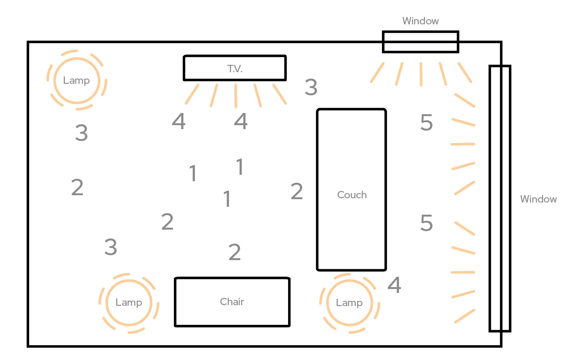
- On a piece of paper, draw the major objects in the room you are sitting in. Are there tables, chairs, windows, doors? Make sure to label them so that anyone could easily read your map and understand the space.
- Walk around the room holding your kit and answer these questions: Where does it spin the fastest? Where is it the slowest? Are there any obstacles that block light or generate light?
- Using these answers, mark your map with the following symbols: Number 5 for the fastest spots, number 1 for the slowest spots, up-arrows for light sources, and down-arrows for light blockers.
- Now fill in the rest of your map with the numbers 2-4 showing where the fan gradually speeds up or gradually slows down.
You’ve now created a light map of your room!
Let's revisit our work so far and answer some questions.
Write down a couple sentences about these questions and share:
- What is data?
- What kind of data is the circuit indicating about my environment?
- What changes can I make to my environment to change how fast my fan spins?
- If you gave your completed kit to someone without explaining it, do you think they could figure out what it does?
That's pretty cool, but... What can we do now?
Part 3: Owning Your Environment
We just mapped our room based on the amounts of light in various areas, but what does this mean? Well, just like in the The Science of Collective Discovery, we want to measure, collect, and be aware of how various aspects of our environment (such as air, water, and light) can impact us. While we don’t often think about light in this way, the amount and quality of light in our spaces can have a huge impact on how we think and feel throughout the course of our day. Studies have shown that increasing our exposure to natural light can boost Vitamin D in our bodies and also help us improve sleep quality. So our project can actually help us and those around us improve the overall quality of where we work, eat, sleep, and live!
What might be the results of the mapping experiment in the room where we do homework? Hang out with friends? Spend time with family?
Most importantly, what are some ways you would imagine changing these spaces to get more light? Share some ideas with the people you share these spaces with, and put your science experiment to use.
Troubleshooting
Here's some things to look for if your project isn't working (and for some great illustrations and further explanations of these, see "Common Mistakes when Using a Breadboard" on the Science Buddies site.)
If your motor doesn’t turn on:
1. Check your connections Be sure to double check the coordinates in the instructions to make sure the pins are completely inserted into the matching holes on the breadboard. Make sure components are fully seated in the breadboard. A component should go into the breadboard at least 4-5 mm (or a little less than the thickness of a pencil) when it's fully inserted. Check for shorts. When components get accidentally connected, it can cause a short circuit.
2. Check your power
Make sure your batteries are fully inserted. Make sure your batteries work.
2. Check the direction(polarity) of your transistor and diode
Make sure the flat side of the transistor (3 pins) is facing toward the jumper wires in C10-12. Make sure the grey strip side of the diode is facing near G21.
Full Kit Contents List
Sometimes, things break or get lost—it's part of making and tinkering! If you need to replace a part, here is a list of the individual components that make up the Red Hat Co.Lab Light Sensing kit.