Qwiic Twist Hookup Guide
 Nate
Nate Introduction
Sometimes you just need a volume knob. The Qwiic Twist is a digital RGB encoder, also known as a continuously rotating knob that is read and controlled over I2C.
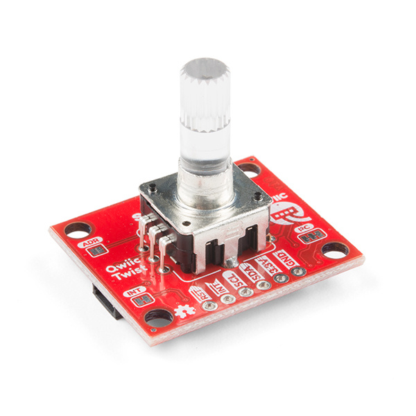
What does that mean? Send the command twist.getCount() and you’ll get the number of steps the user has twisted the knob. For example, 312 or -23 depending on the direction and amount the user and turned the knob. The Twist takes care of all the various interrupts, switches, PWM'ing of LEDs and presents all those features over an easy-to-use I2C interface. The Qwiic Twist was designed to get rid of the large mass of wires that are needed to implement an RGB encoder in a breadboard. Now you can get encoder position with something as twist.getCount(); and your microcontroller can keep focused on other more important tasks.
The Qwiic Twist has an indent type encoder which gives the user a great 'clicky' feel as they turn. The Qwiic Twist also has an RGB LED and a built-in button. We’ve written an Arduino library to make controlling these features as easy as:
language:c
twist.setColor(255, 0, 0); //Red
if(twist.isPressed() == true) Serial.println(“Pressed!”);
And finally, the I2C address of Qwiic Twist is software configurable which means you can hookup over 100 Twists on a single I2C bus!
Required Materials
To follow along with this hookup guide, you will need one of the following Qwiic shields with an Arduino. You may not need everything though depending on what you have. Add it to your cart, read through the guide, and adjust the cart as necessary.


You will also need a Qwiic cable to connect the shield to your Twist, choose a length that suits your needs. The Qwiic to breadboard cable is good if you want to easily plug the Qwiic Twist into a 3.3V platform such as Teensy.
Qwiic Cable - Breadboard Jumper (4-pin)
PRT-14425
Qwiic Cable - 50mm
PRT-14426
Qwiic Cable - 100mm
PRT-14427
Qwiic Cable - 200mm
PRT-14428
Qwiic Cable - 500mm
PRT-14429Tools
The Qwiic Twist is designed to be easily connected to a Qwiic bus without soldering. But if you choose to connect to the I2C pins directly you may need a soldering iron, solder, and general soldering accessories.


Weller WLC100 Soldering Station
TOL-14228Suggested Reading
If you aren't familiar with the Qwiic system, we recommend reading here for an overview.
| Qwiic Connect System |
We also recommend checking out these tutorials before continuing.
I2C
Qwiic Shield for Arduino & Photon Hookup Guide
Additionally, we’ve got a great video on how the inner workings of encoders work and why they’re important.
Hardware Overview
The RGB encoder is a 24 indent encoder. You’ll feel 24 clicks when turning one 360 degree rotation.
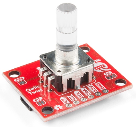
The encoder works best with the Clear Plastic Knob but is compatible with any knob with a 6mm knurled hole. The encoder output is filtered through a series of resistors, capacitors, and error checked in software to be sure the accurate number of ticks is being output.
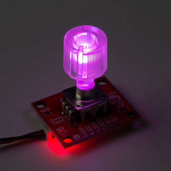
The encoder has an RGB LED built into it. To get the full light effect we recommend a clear knob but depending on your setup you may also be able to get a ‘backlit’ effect with an opaque knob. The RGB LEDs are pulse-width-modulated and controlled via software (and backed by non-volatile memory) so you can tell the Qwiic Twist to go to any color you want and it will be that color now and even after the Twist is power cycled (it remembers the last color setting).
The encoder has a built-in momentary button. This is useful for selecting menu items and getting general feedback from the user.
Qwiic I2C Pins
The Qwiic Twist is best used with the Qwiic system. Simply plug a Qwiic Cable into the Twist and start talking to it.
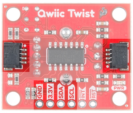
Alternatively you can solder to the I2C pins on the board.
RST and INT
The reset pin is an active low input. When pulled low Qwiic Twist will be held in reset.
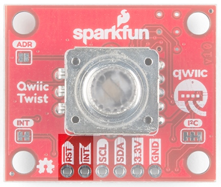
The INT pin is active low and is open drain output. The interrupt pin will go low when any of the follow events happen:
- The user presses the button is pressed or released.
- The user has turned the knob and no movement has been detected for a certain amount of time. This amount of time is called the turnInterruptTimeout and is 250ms by default. This means that once the user has stopped turning the knob for 250ms the interrupt will fire. This is helpful when the user is doing lots of knob changes. The Qwiic Twist won't fire the interrupt until the user has stopped fidgeting. The turnInterruptTimeout is software configurable from 1ms to 65000ms (65 seconds).
The INT pin is open drain and is pulled up through a 10k resistor but if you want to connect multiple Twists and share the interrupt pins among many Twists then you can optionally cut the jumper to remove the 10k pull up on each Twist board.
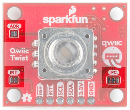
Jumpers
The ADR jumper is normally open and controls the I2C address of the device. By default the Qwiic Twist 7-bit unshifted address is 0x3F. If the jumper is closed with solder, the address will become 0x3E.
The Twist is unique in that it can have any address assigned to it between 0x08 and 0x77. This means over 100 Twists can be connected on a single bus!
Note: If the ADR jumper is closed then Qwiic Twist will resort to address 0x3E regardless of what address may have been configured via software commands. This is a safety mechanism in case the Twist gets set to an unknown address.
The INT jumper is a normally closed jumper; there is a small trace connecting the two pads. This jumper connects the INT pin on the ATtiny84 through a 10k resistor to 3.3V. Cutting the small trace disconnects the 10k resistor from the INT pin on the ATtiny84.
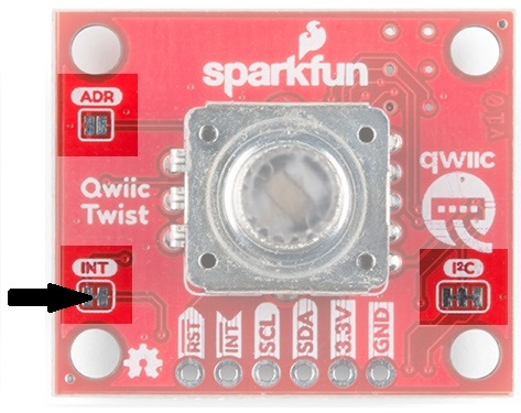
The INT pin on Qwiic Twist is open drain, meaning the pin will actively go low when an interrupt occurs but will then float when there is no interrupt. This open drain type of setup is handy if you have multiple devices sharing a single interrupt line. For advanced applications (such as many many Twists all sharing the same INT pin) you may want to cut this jumper on each Twist to remove the 10k pull ups. For general use you can leave this jumper unmodified.
The Qwiic Twist has built-in 2.2k pull-up resistors on the SDA and SCL lines. These are needed for normal I2C communication. The I2C jumper has two small traces connecting the pull-ups to 3.3V. For general use you can leave this jumper unmodified. If you have many (over 7) devices on the I2C bus, each with their own pull up resistors, then you may want to cut the I2C jumpers to disconnect the 2.2k resistors on each Qwiic board.
Qwiic Twist Arduino Library
We’ve written an easy to use Arduino library that covers the gamut of features on the Qwiic Twist. The easiest way to install the library is by searching SparkFun Twist within the Arduino library manager. We’ve even got a tutorial on installing an Arduino library if you need it. You can also manually install the Qwiic Twist library by downloading a zip:
- Example 1 - Basic reading of the encoder value
- Example 2 - Set the Knob Color
- Example 3 - Displaying Crazy Colors on Knob
- Example 4 - Connect Colors: Change knob color from blue to red based on position
- Example 5 - Reading Time Stamps
- Example 6 - Display encoder difference since last reading
- Example 7 - Set the encoder count value
- Example 8 - Enabling and reading interrupts
- Example 7 - Set the encoder count value
- Example 9 - Change the I2C address
- Example 10 - Advanced Wire settings
Below are the various functions that can be called from the library. Most of these functions are demonstrated in the examples so we recommend you go through each example first.
boolean begin(TwoWire &wirePort, uint8_t deviceAddress);int16_t getCount();-- Returns the number of indents the user has turned the knobboolean setCount(int16_t amount);-- Set the number of indents to a given amountint16_t getDiff(boolean clearValue = true);-- Returns the number of ticks since last check. Clears the difference once read.boolean isMoved();-- Returns true if knob has been twistedboolean isPressed();-- Return true if button is currently pressed.boolean isClicked();-- Returns true if a click event has occurred. Event flag is then reset.uint16_t timeSinceLastMovement(boolean clearValue = true);-- Returns the number of milliseconds since the last encoder movement. Clears value once read.uint16_t timeSinceLastPress(boolean clearValue = true);-- Returns the number of milliseconds since the last button event (press and release). Clears value once read.
Color functions set the brightness of each LED.
boolean setColor(uint8_t red, uint8_t green, uint8_t blue);-- Sets the color of the encoder LEDs, 0-255boolean setRed(uint8_t);-- Set the red LED, 0-255boolean setGreen(uint8_t);-- Set the green LED, 0-255boolean setBlue(uint8_t);-- Set the blue LED, 0-255uint8_t getRed();-- Get current valueuint8_t getGreen();-- Get current valueuint8_t getBlue();-- Get current value
Connect functions set the relation between each color and the twisting of the knob. These functions connect the LED so it changes [amount] with each encoder tick without the master intervening. Negative numbers are allowed (so LED gets brighter the more you turn the encoder down).
boolean connectColor(int16_t red, int16_t green, int16_t blue);-- Connect all colors in one commandboolean connectRed(int16_t);-- Connect individual colorsboolean connectGreen(int16_t);-- Connect individual colorsboolean connectBlue(int16_t);-- Connect individual colorsint16_t getRedConnect();-- Get the connect value for each colorint16_t getGreenConnect();int16_t getBlueConnect();
General functions get and set various aspects of the Twist.
uint16_t getIntTimeout();-- Get number of milliseconds that must elapse between end of knob turning and interrupt firingboolean setIntTimeout(uint16_t timeout);-- Set number of milliseconds that elapse between end of knob turning and interrupt firingvoid clearInterrupts();-- Clears the moved and button interrupts as well as the pressed and clicked event bitsboolean isConnected();-- Returns true if sensor is detecteduint16_t getVersion();-- Returns a two byte firmware versionvoid changeAddress(uint8_t newAddress);-- Change the I2C address to newAddress
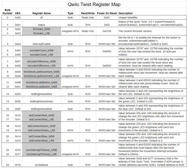
Register Map
If you’d like to use a platform other than Arduino you can easily control Qwiic Twist by accessing the following set of registers:
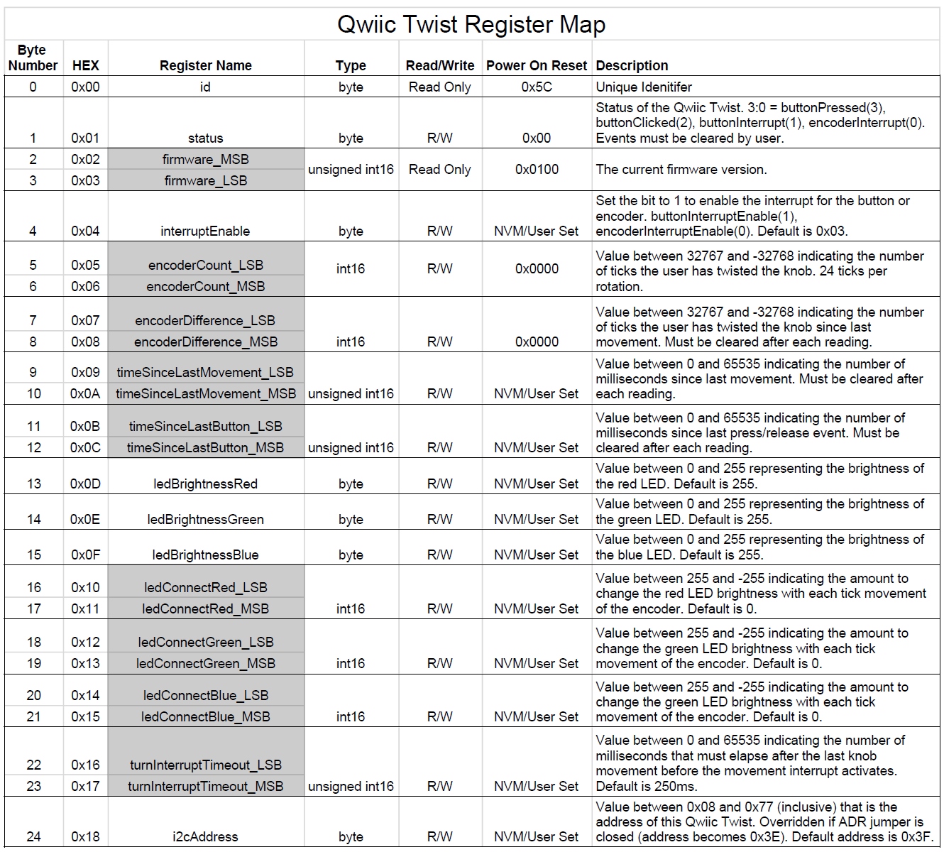
The Qwiic Twist behaves as a normal I2C peripheral. First write the address of the register you would like to read or write, then follow that I2C command with a Read to read the given register or a Write and a data byte to write to a register. The register address pointer is auto-incrementing so you can read and write multiple registers at a time.
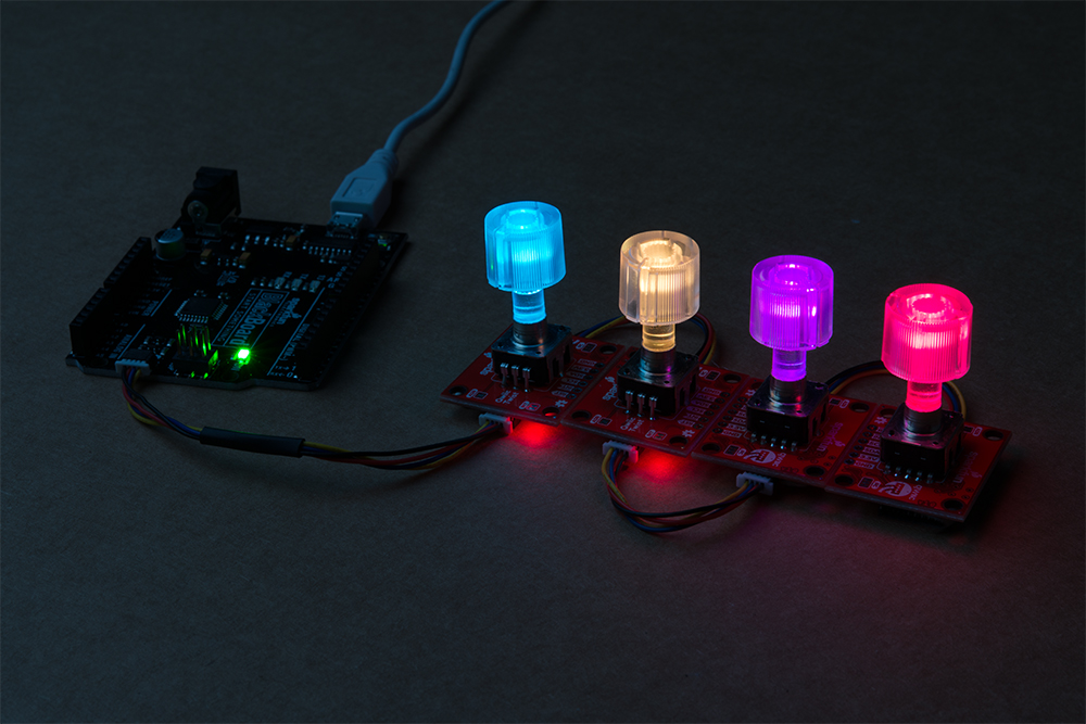
Connecting Colors
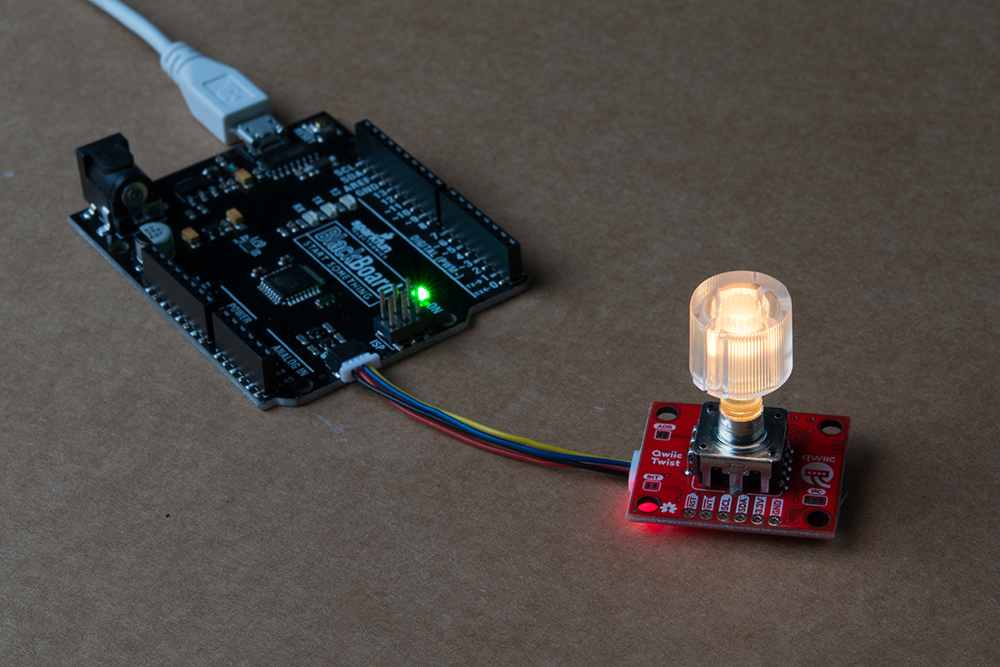
One of the more advanced (but really handy) features of Qwiic Twist is the ability to connect the color control to the knob movement. What this means is that you can have the red LED brightness increase or decrease as the user turns the knob without sending commands to the Qwiic Twist. This greatly increases the responsiveness of the knob illumination and dramatically reduces I2C traffic.
In the above photo we have connected blue to increase brightness by 10 for every tick increment, and connected red to -10 per tick. The color changes automatically without the need for intervention from the I2C master. The color connect values are stored in the Qwiic Twist and will be loaded after each power-on.
See Example4 of the SparkFun library for a full demonstration.
Resources and Going Further
Looking for more information? Check out the links provided here:
- Schematic (PDF)
- Eagle (ZIP)
- Qwiic Twist Register Map
- GitHub Repo
- SparkFun Qwiic Twist Arduino Library - for easy interfacing to the Qwiic Twist including a litany of examples. This is most easily installed by searching the Arduino Library Manager for ‘SparkFun Twist’.
- SparkFun Qwiic Twist Python Package - for interfacing with the Qwiic Twist on a Raspberry Pi or Jetson Nano. This is most easily installed with the instructions here.
- Hardware repo - For Qwiic Twist that includes the firmware for the ATtiny84
- SFE Product Showcase
We hope you have a lot of fun with your Qwiic Twist! Check out these other Qwiic products:
Qwiic VR IMU (BNO080) Hookup Guide
IoT RedBoard ESP32 Development Board Hookup Guide
MicroMod Qwiic Pro Kit Project Guide
Sending Sensor Data over LoRa
Or check out this blog post for ideas.