Qwiic Real Time Clock Module (RV-1805) Hookup Guide
 Englandsaurus
Hardware Overview
Let's look over a few characteristics of the RV-1805 RTC so we know a bit more about how it behaves.
| Characteristic | Range |
|---|---|
| Operating Voltage (Startup) | 1.6V - 3.6V |
| Operating Voltage (Timekeeping) | 1.5V - 3.6V |
| Operating Temperature | -40°C - 85°C |
| Time Accuracy | ±2.0 ppm |
| Current Consumption | 22 nA (Typ.) |
| I2C Address | 0x69 |
Pins
The characteristics of the available pins on the RTC are outlined in the table below.
| Pin Label | Pin Function | Input/Output | Notes |
|---|---|---|---|
| 3.3V | Power Supply | Input | Should be between 1.95 - 3.6V |
| GND | Ground | Input | 0V/common voltage. |
| SDA | I2C Data Signal | Bi-directional | Bi-directional data line. Voltage should not exceed power supply (e.g. 3.3V). |
| SCL | I2C Clock Signal | Input | Master-controlled clock signal. Voltage should not exceed power supply (e.g. 3.3V). |
| PSW | Power Switch | Output | Power Switch pin, digital output. Capable of switching power on an external microcontroller. |
| INT | Interrupt | Output | Interrupt pin, active low, digital output. Also configurable as a square wave up to 32.768 kHz |
| RST | Reset | Output | Reset pin, active low, digital output |
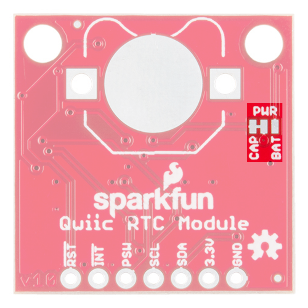
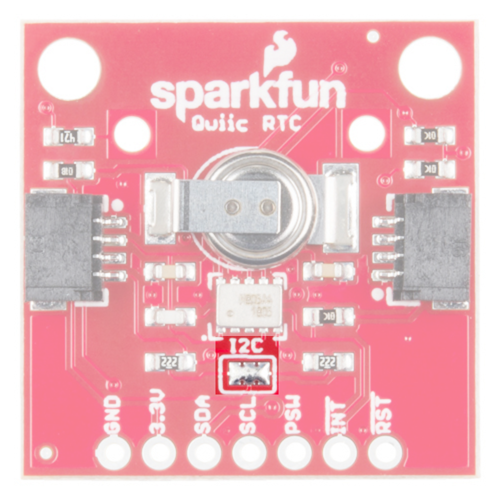
Optional Features
The Qwiic RTC has onboard I2C pull-up resistors; if multiple sensors are connected to the bus with the pull-up resistors enabled, the parallel equivalent resistance will create too strong of a pull-up for the bus to operate correctly. As a general rule of thumb, disable all but one pair of pull-up resistors if multiple devices are connected to the bus. If you need to disconnect the pull up resistors they can be removed by removing the solder on the corresponding jumpers highlighted below.
There is also the option to add a battery to the board if the supercapacitor just isn't gonna keep your project powered long enough (keep in mind, the supercap can hypothetically make the board keep time for around 35 days) you can solder on an external battery. Keep in mind that if doing so, you'll need to cut the trace connecting power to the capacitor, and add solder to the side of the jumper that connects power to the battery labeled as BAT.