Qwiic Real Time Clock Module (RV-1805) Hookup Guide
 Englandsaurus
Example Code
Example 1 - Set Time
Once you've installed the SparkFun Qwiic RTC RV-1805 Arduino library go to File > Examples > SparkFun Qwiic RTC RV-1805 Arduino Library > Example1-Set_Time to open the example sketch. We will use this first sketch to set up our RTC's internal clock. Take note of the following lines of code, which use the compiler time to set the RTC's clock.
language:c
if (rtc.setToCompilerTime() == false) {
  Serial.println("Something went wrong setting the time");
}
Note that this doesn't reset every time we upload code into our Arduino, so make sure you restart the IDE before uploading to get the most current time to upload into your RTC.
Example 2 - Print Time
Now that we've set the time on the RTC, let's read it out. Open the next example by heading to File > Examples > SparkFun Qwiic RTC RV-1805 Arduino Library > Example2-Print_Time to open the example sketch. After initializing the RTC object, we attempt to update the time variables in our microcontroller with the values from the RTC using some of the code below. If this is successful, we print them out.
language:c
if (rtc.updateTime() == false) //Updates the time variables from RTC
  {
    Serial.print("RTC failed to update");
  }
Also, in its need to feel special, the United States formats its dates differently than the rest of the world (We do MM/DD/YYYY format while everybody else does DD/MM/YYYY format). So if you don't live in the U.S. or you just like how the rest of the world formats their dates, you'll need to uncomment the following line of code (line 50) in your sketch.
language:c
//String currentDate = rtc.stringDate());
Once you upload this code to your microcontroller, go ahead and open the serial monitor with a baud rate of 9600. You should see the current date and time go streaming past, looking something like the image below.
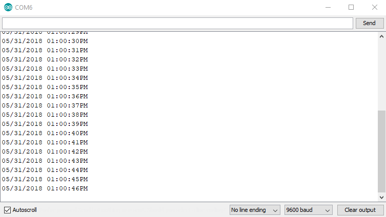
If your output is showing the incorrect time, you may need to recompile your sketch to get the latest compiler time using the code from the first example. If this doesn't work, try restarting the Arduino IDE to get a new compiler time.
Example 3 - Trickle Charging
To pull up the next example, go to File > Examples > SparkFun Qwiic RTC RV-1805 Arduino Library > Example3-Trickle_Charging. This example will show us how to fiddle with the RTC's trickle charging circuit to configure it for different charge rates as well as disable it if we want to use a coin cell battery.
The trickle charge circuit consists of a diode (0.3v or 0.6v drop) in series with a resistor (3kOhm, 6kOhm, or 11kOhm) These are available to pass into the function as DIODE_0_3V, DIODE_0_6V, ROUT_3K, ROUT_6K, ROUT_11K. The fastest possible rate, with a 0.3V diode and 3kOhm resistor is enabled by default. Note that the trickle charger should only be used for charging the supercapacitor. Disable the trickle charger simply by calling disableTrickleCharge() if you've connected the optional battery.
Example 4 - Alarm Interrupt
To pull up the next example, go to File > Examples > SparkFun Qwiic RTC RV-1805 Arduino Library > Example4-Alarm_Interrupt. This example shows how to enable and use the alarm interrupt to generate an interrupt every time some or all of the alarm registers match the time register. First, we need to set up what time we want the alarm to go off. To do this, we set the variables in the preamble to the time we would like. They default to the values below as these are the default alarm values.
language:c
byte secondsAlarm = 0;
byte minuteAlarm = 0;
byte hourAlarm = 0;
byte dateAlarm = 0;
byte monthAlarm = 0;
Next, we need to set which parts of the time must match in order for the alarm to be triggered. to do this, we use the setAlarmMode(uint8_t mode); where mode is a number between 0 and 7. Go to line 60 (in the setup loop) if you'd like to change how often the alarm is triggered. The values corresponding to which registers much match are listed below.
0: Disabled1: Hundredths, seconds, minutes, hours, date and month match (once per year)2: Hundredths, seconds, minutes, hours and date match (once per month)3: Hundredths, seconds, minutes, hours and weekday match (once per week)4: Hundredths, seconds, minutes and hours match (once per day)5: Hundredths, seconds and minutes match (once per hour)6: Hundredths and seconds match (once per minute)7: Depends on the alarm value for hundredths.0-99: Hundredths match (once per second)240-249: Once per tenth (10 Hz)255: Once per hundredth (100 Hz)
Once you've set the alarm to your liking, go ahead and upload the code to your microcontroller. The interrupt pin will now drop low every time the alarm is triggered. If you don't want to physically check the status of the interrupt pin, you can uncomment the section of code in the void loop that reads the status register of the RTC. This will alert you when the alarm has been triggered.
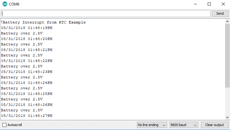
Example 5 - Battery Interrupt
To pull up the next example, go to File > Examples > SparkFun Qwiic RTC RV-1805 Arduino Library > Example5-Battery_Interrupt to open the example sketch. This example checks the charge level of the supercapacitor and alerts the user when it has reached 2.5V. You can change the voltage level at which the user is alerted by changing the values passed into checkBattery(voltage, edgeTrigger);. Follow the chart on the Library Overview page to select the proper voltage. Once you've uploaded the example code to your microcontroller, go ahead and open the serial monitor to 9600 baud. The output should look something like the image below once the RTC is charged to the selected voltage.