Qwiic Pressure Sensor (BMP581) Hookup Guide
Hardware Overview
In this section we'll take a closer look at the hardware present on these Qwiic Pressure Sensor - BMP581 breakouts.
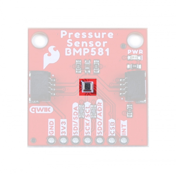
BMP581 Pressure Sensor
The BMP581 is an extremely precise and versatile absolute pressure sensor from Bosch Sensortec that uses on-chip linearization and temperature compensation to provide true absolute pressure and temperature data.
 |
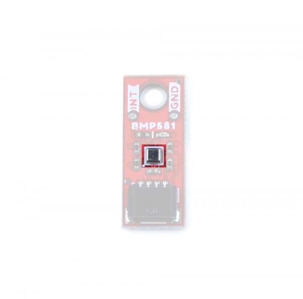 |
The BMP581 features a wide pressure sensing range (30 to 125 kPa), pressure data resolution of 1/64 Pa with excellent accuracy across the sensing range (± 0.5 hPa (max)) as well as output data rates up to 622 Hz. All of this in a package size of just 2.0 mm2!
The sensor accepts a supply voltage of 1.71V to 3.6V though the board runs the sensor at 3.3V. The BMP581 includes a FIFO buffer that can store up to 32 samples, user-programmable low-pass filtering as well as configurable IIR settings to help offset noise created by ambient changes in pressure such as doors/windows opening or closing or wind passing by the sensor. Lastly, the BMP581 even has 6 bytes of user-programmable non-volatile memory.
The table below outlines some of the BMP581's sensing parameters. For a full overview of the BMP581, refer to the datasheet.
| Parameter | Min. | Typ. | Max. | Units | Notes |
|---|---|---|---|---|---|
| Operating Temperature | -40 | 25 | 85 | °C | |
| Operating Pressure | 30 | - | 125 | kPa | |
| Relative Accuracy | - | ±0.06 | - | hPa | Per 10 kPa step. |
| Absolute Accuracy | - | - | ±0.5 | hPa | |
| Temp. Coeff. Offset | - | ±0.5 | - | Pa/K | At 900hPa & 25-40°C |
| Pressure Noise1 | - | 0.78 | .095 | PaRMS | Oversampling rate set to "Lowest Power". |
| - | 0.21 | 0.25 | PaRMS | Oversampling rate set to "High Resolution". | |
| - | 0.08 | PaRMS | Oversampling rate set to "Highest Resolution". | ||
| Output Data Rate 1 | 0.125 | - | 240 | Hz | Range is for Normal Mode. |
The sensor has seven operating modes outlined in the table below. For complete information on the power modes and configuration settings available or required for them, refer to section 4.3 of the datasheet:
| Operating Mode | Power Consumption (@25°C and VDDIO/VDD=3.3V) | Notes |
|---|---|---|
| Standby | 1.0µA (.typ) | Saves the last pressure/temperature values measured as well as FIFO data (if enabled). |
| Deep Standby | 0.55µA (typ.) | Most efficient power consumption. Entering Deep Standby requires a specific set of conditions. Refer to section 4.3.2 of the datasheet for more information. |
| Forced | Single-shot measurements taken according to measurement and filter options. Sensor returns to sleep mode. Measurements available for reading on the data registers. Must return sensor to forced mode for next measurement. | |
| Normal | 260µA (max) | Sensor performs measurements on a configured frequency set as the Output Data Rate (ODR). The sensor cycles between active measurements and standby periods. |
| Low Power Normal | 1.3µA (typ.) | Operates the same as Normal Mode but enters Deep Standby mode in between measurement periods. |
| Continuous | 260µA (max) | Sensor performs measurements at the maximum frequency possible with the selected oversampling settings. Sensor remains in the active measurement with no cycling to a standby period. |
| Sleep | The sensor must be put into Sleep Mode when transitioning between any of the operating modes. |
Communication Interfaces - I2C & SPI
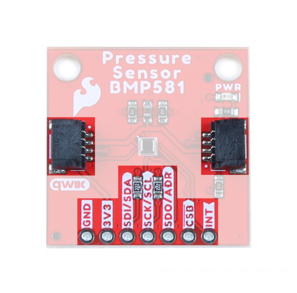
The standard size Qwiic Pressure Sensor (BMP581) communicates over I2C by default but also supports using the BMP581 over SPI. The Qwiic Micro version only supports I2C over the Qwiic connector on the board.
 |
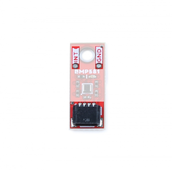 |
The breakout routes the I2C interface to a pair of Qwiic connectors as well as a 0.1"-spaced PTH header for users who prefer a traditional, soldered connection. This PTH header shares the SPI connections and also includes the Interrupt pin.
The board sets the BMP581's I2C address to 0x47 by default. Adjust the ADR jumper to change to the alternate address (0x46) or leave it completely open to use the SPI interface (Standard size only). More information on this jumper in the Solder Jumpers section below.
Solder Jumpers
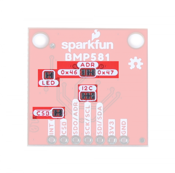
The standard size breakout has four solder jumpers labeled: I2C, ADR, CSB and LED. The micro size breakout has all but the CSB jumper since the micro version does not support SPI.
 |
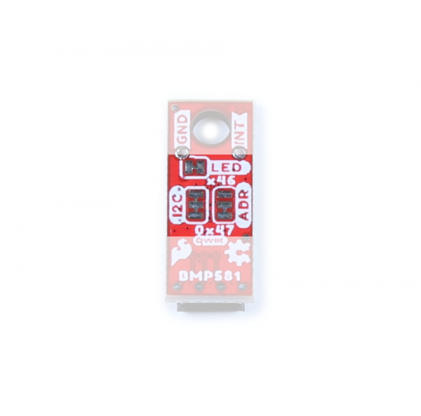 |
The I2C jumper connects a pair of 2.2kΩ resistors to the SDA/SCL lines. Leave these enabled unless you have a large number of I2C devices on the same bus.
The ADR jumper sets the I2C address of the BMP581 to 0x47 by default (0x46 alternate). It also controls whether it operates via I2C or SPI. Open the jumper completely to set the BMP581 to communicate via SPI.
The CSB jumper pulls the Chip Select pin to VDD (3.3V) through a 10kΩ resistor. Open the jumper to disable the pullup.
The LED jumper completes the Power LED circuit. Open the jumper to disable the Power LED if desired.
Board Dimensions
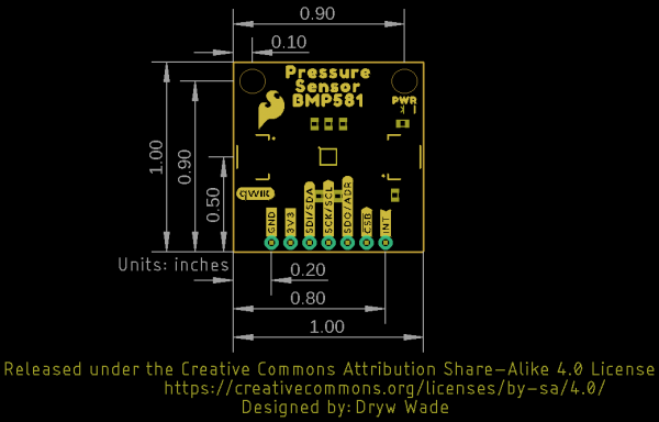
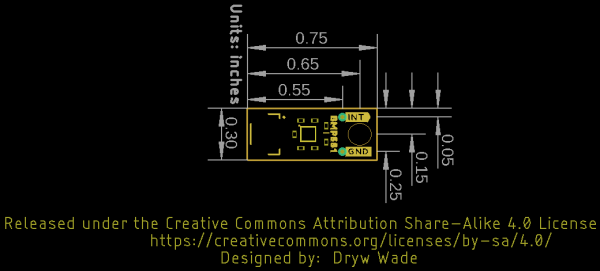
The standard size Qwiic breakout matches the 1.0" x 1.0" (25.4mm x 25.4mm) form factor for Qwiic breakouts with two mounting holes that fit a size 4-40 screw. The Micro version of this breakout matches the Qwiic Micro form factor and measures 0.75" x 0.30" (24.65mm x 7.62mm) and has one mounting hole that fits a size 4-40 screw.
 |
 |