$2.50
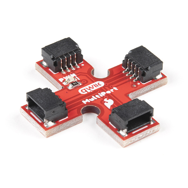
The SparkFun Qwiic Multiport adds additional ports to boards that have only one Qwiic port on their I2C bus. Once added, you can use it as a hub to add as many I2C devices to the bus as you need [1] ! You can also use the board as an alternative to a daisy chained configuration.
To follow along with this tutorial, you will need a microcontroller or single board computer with a Qwiic connector. You will also need a Qwiic cable and a way to power the board. You may not need everything though depending on what you have. Add it to your cart, read through the guide, and adjust the cart as necessary.
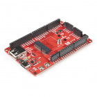
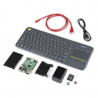
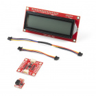
Besides having the Qwiic MultiPort in your cart, here are the parts if you decide to go with a microcontroller. You can easily swap out the microcontroller depending on your project's needs with MicroMod. Make sure to include the Qwiic-enabled device in your cart as well!
Here are the parts if you decide to go with a single board computer. The Qwiic SHIM kit is a great starting point if you do not have a Qwiic-enabled device in mind.
If you aren't familiar with the MicroMod ecosystem, we recommend reading here for an overview. We recommend reading here for an overview if you decide to take advantage of the Qwiic connector.
 |
|
| MicroMod Ecosystem | Qwiic Connect System |
We also recommend taking a look through the following tutorials if you are not familiar with the concepts covered in them:
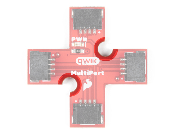
The board is a simple design that allows you to connect devices to the I2C bus easily with the Qwiic Connect System. Power and logic levels are set to 3.3V. Make sure to use a logic level converter if your board uses a voltage higher than 3.3V.
| Wire Color | Signal |
|---|---|
| Black | GND |
| Red | 3.3V |
| Blue | SDA |
| Yellow | SCL |
There are 4x Qwiic connectors populated on the board.
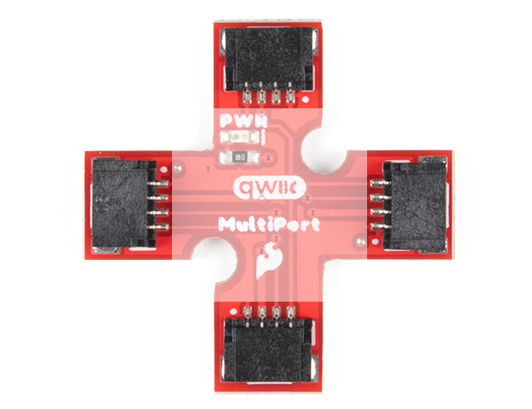
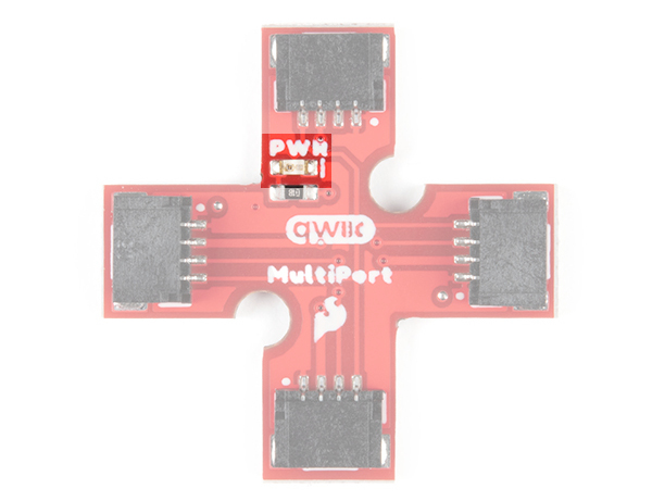
In addition to the connectors, there is an LED to indicate when power is available on the I2C bus. On the back, there is a jumper in case you would like to disable the LED.
 |
 |
| Front of Board | Back of Board |
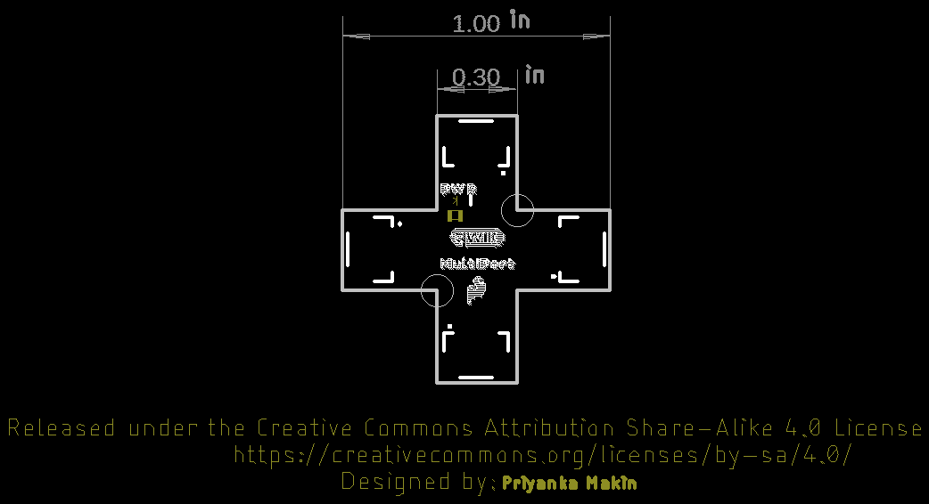
There are 2x mounting holes included on the board.
Below are the board dimensions. The overall size of the board is 1.00" x 1.00". Each connector extending from the center has a width of about 0.30". As stated earlier, this board has 2x mounting holes located around the center.
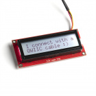
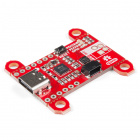
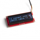
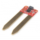
Depending on the design, there may only be enough room for one Qwiic connector. Below are a few of these boards from the SparkFun catalog
If you are looking to connect more than one device with one Qwiic connector to your development board, you will just need a Qwiic MultiPort board and an additional Qwiic cable for each device.
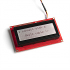
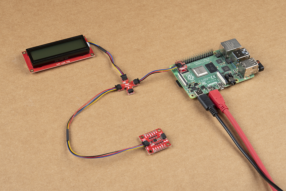
The Qwiic MultiPort can also be used as a hub so that you do not have to place the board with one Qwiic connector at the end of the daisy chain. Below is an example with the Qwiic SHIM Kit for Raspberry Pi. Instead of having the Qwiic 9DoF between the Pi and Qwiic SerLCD,
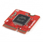
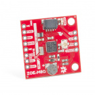
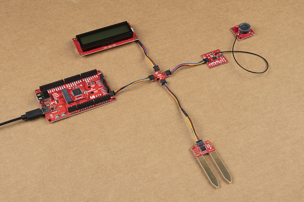
The two boards can be mounted with standoffs for a secure connection. Below is the Qwiic Micro (SAMD21), Qwiic MultiPort, Qwiic GPS (ZOE-M8Q), and a GPS antenna (W3062A) connected stacked on top of each other. They are all connected to the Qwiic SerLCD connect using Qwiic cables (with the exception of the antenna).

Now that you've connected your Qwiic MultiPort, it's time to incorporate it into your own project! For more information, check out the resources below:
Looking for inspiration? Check out any of the tutorials tagged with Qwiic for ideas on what to connect to your Qwiic system!
learn.sparkfun.com | CC BY-SA 3.0 | SparkFun Electronics | Niwot, Colorado