Qwiic LED Stick - APA102C Hookup Guide
 El Duderino, MAKIN-STUFF
Hardware Overview
The Qwiic LED Stick is a fairly straightforward ATTiny85-based Qwiic board that you may be familiar with already. In this section we'll cover the hardware present on the board in detail.
ATTiny85
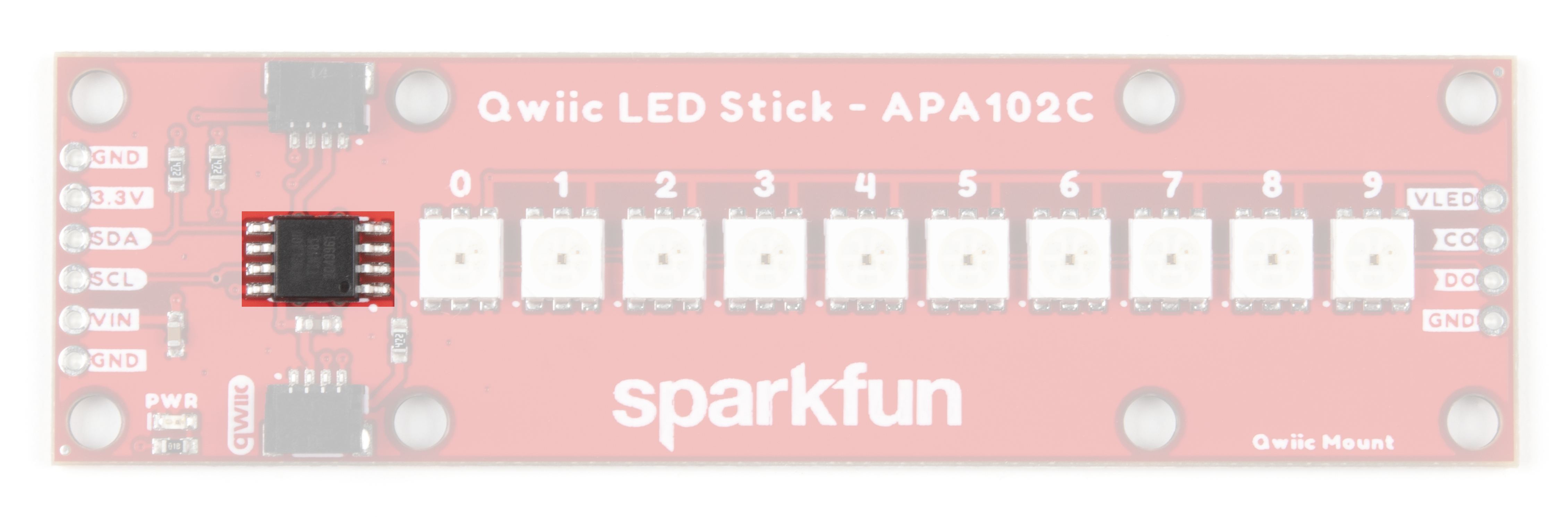
The brains of the Qwiic LED Stick is one of our favorite microcontrollers, the ATTiny85. This IC comes pre-programmed with custom firmware designed to interact with the Arduino library and Python package we've written to use with this board. The ATTiny85 accepts I2C reads and writes, interprets them and outputs the appropriate strings to control any APA102 LEDs attached to it.
The default I2C address of the ATTiny85 is 0x23. Adjust the address either through the ADR jumper or via software. Read on for more information regarding changing the address in both manners.
Just like our other Qwiic breakouts using the ATTiny85, users can update or change the firmware using the 2x3 pin header on the back of the board. The firmware can be found in the Hardware GitHub Repository. For tips and tricks on how to re-program an ATTiny IC, check out this tutorial.
APA102C LEDs
The LED Stick includes 10 APA102C LEDs controlled by the aforementioned ATTiny85. APA102C LEDs operate just like most addressable LEDs over a two-wire interface. The board ties that interface to the ATTiny85 and operates both the IC and LEDs at 3.3V logic. For specific information regarding the LEDs, take a look at the APA102C Datasheet.

The board includes a dedicated power PTH pin labeled VIN (along with a spare Ground PTH) to power the LEDs directly for longer chains of Qwiic LED Sticks or circuits with an extra LED strip that require more power than a typical microcontroller can provide. Enable this power input by adjusting the VLED jumper. The APA102C LED accepts a supply voltage between 3.0V and 5.5V.
We've also routed the LED control signals out to a dedicated 0.1"-spaced PTH header on the edge of the board in case you would like to add another APA102 LED strip to the end of the LED stick. This PTH header has signal labels as well as silk labels on the bottom of the board for the coordinating wire colors (Red, Blue, Green and Yellow) to make it easy to match the wires for standard APA102 LED strips.
Qwiic and I2C Interface
As the product name suggests, the LED Stick routes the I2C interface on this board to a pair of Qwiic connectors for easy assembly using the Qwiic system. Those who prefer a a traditional soldered connection for the circuit can use the I2C pins routed to a standard 0.1"-spaced PTH header.

3.3V and GND are also provided via the Qwiic interface to power both the ATTiny85 as well as the APA102C LEDs in the default configuration.
Solder Jumpers
The Qwiic LED Stick has four solder jumpers labeled I2C, VLED, ADR and LED. Let's take a closer look at them and their functionality. If you've never worked with solder jumpers before or would like a refresher, take a look at our How to Work with Jumper Pads and PCB Traces tutorial.
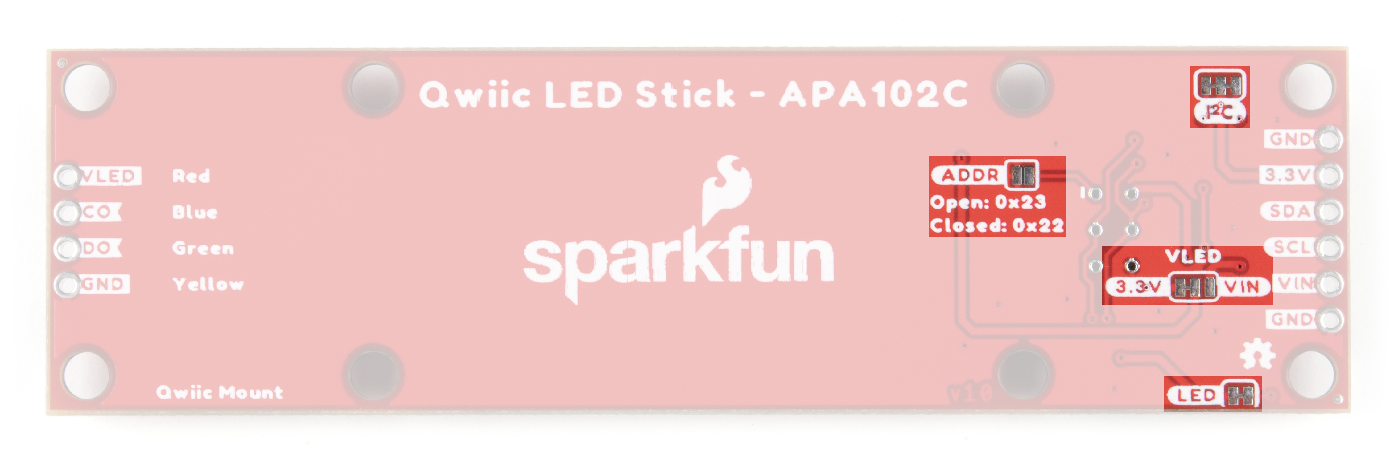
The I2C jumper pulls the SDA/SCL lines on the ATTiny85 to 3.3V via a pair of 4.7kΩ resistors. Disable these pull up resistors by severing the trace between the three pads. Recommended practice is to only have a single pair of pull up resistors enabled on an I2C bus to avoid communication errors caused by too strong of a parallel resistance. If you are using multiple Qwiic LED Sticks or other I2C devices in a long chain, we recommend disabling all but one of these resistor pairs.
The VLED jumper controls the input voltage for the APA102C LEDs. By default, this two-way jumper ties the APA102C VCC to 3.3V provided either over the Qwiic connector or the labeled PTH pin. For long chains of Qwiic LED Sticks, switch this jumper to the VCC side by severing the trace between the center and 3.3V pad and adding a blob of solder to connect the center pad with the VCC side. Once this is adjusted, connect a separate voltage between 3.0V and 5.5V to the VIN PTH pin to power the circuit. When in the VIN position, the board connects a 4.7µF decoupling capacitor to help smooth out power supplied to the LEDs.
The ADR jumper sets the I2C address of the ATTiny85 via a hardware adjustment and is OPEN by default. While open, the ATTiny85's address is set to 0x23. Closing this jumper adjusts the address to 0x22.
The LED jumper controls the board's power LED by tying the anode to 3.3V via a 1kΩ resistor. The jumper is CLOSED by default. Sever the trace between the two pads to disable the power LED if needed.
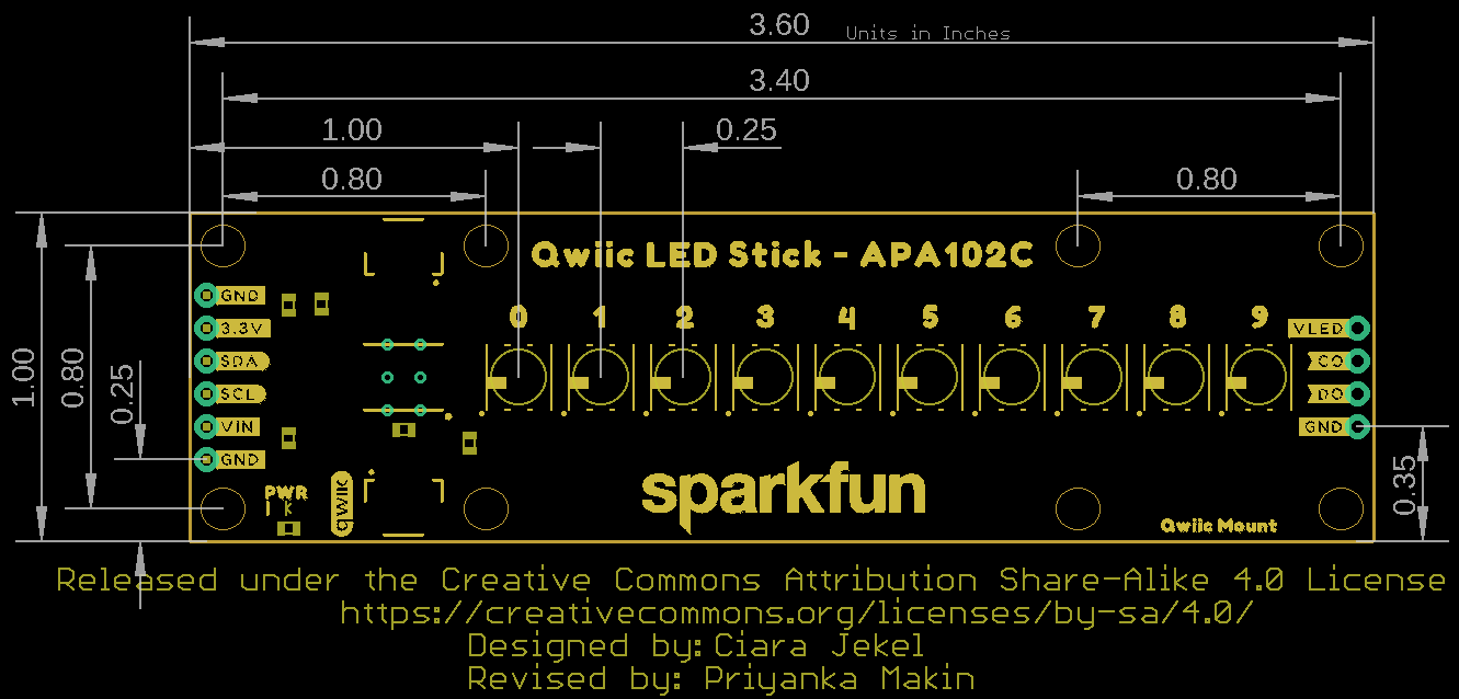
Board Dimensions
The Qwiic LED Stick measures 1.00in x 3.60in (25.4mm x 91.44mm) with four mounting holes that fit a 4-40 screw.