Qwiic Joystick Hookup Guide
Hardware Overview
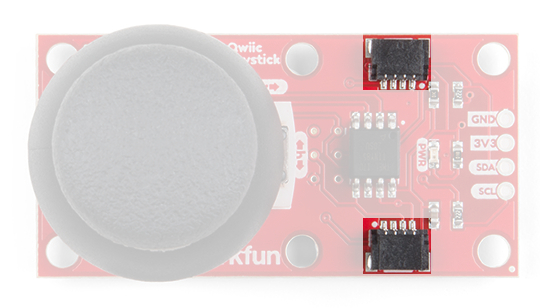
The Qwiic Joystick will report the thumbstick position over I2C and is designed to be compatible with the Qwiic system so you can add it to your project solder-free!
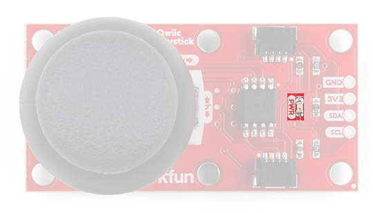
Power LED
There is a power status LED to help make sure that your Qwiic Joystick is getting power. You can power the board either through the polarized Qwiic connector system or the breakout pins (PWR and GND) provided. The Qwiic system is meant to run on 3.3V, be sure that you are NOT using another voltage when using the Qwiic system.
Joystick
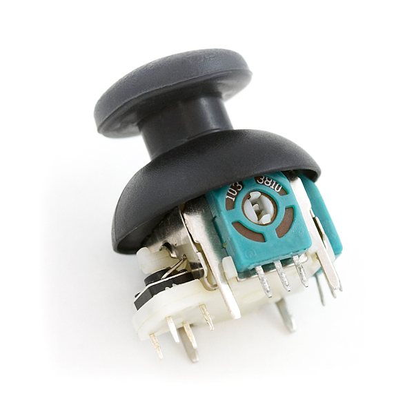
The joystick is similar to the analog joysticks on PS2 (PlayStation 2) controllers. Directional movements are simply measured with two 10 kΩ potentiometers, one for each axis. This joystick also has a select button that is actuated when the joystick is pressed down.
The two potentiometers are connected to the analog to digital converter (ADC) of the ATtiny85. The select button operates as a digital input on the ATtiny85. This allows the firmware to read the knob position and any button presses.
Joystick Orientation
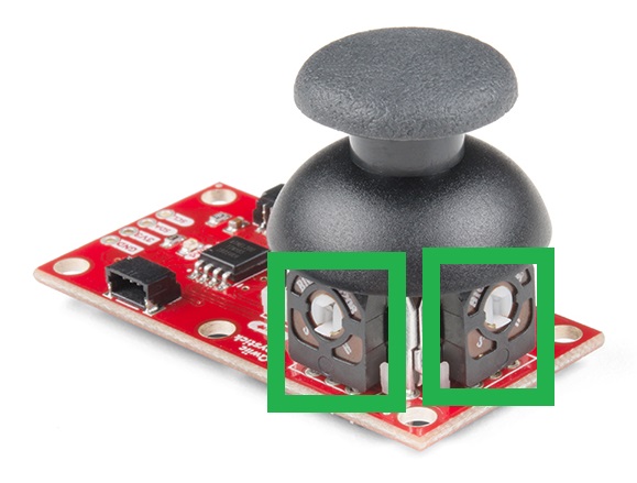
The joystick contains two potentiometers, connected with a gimbal mechanism that separates the horizontal and vertical movements (orientation shown below).
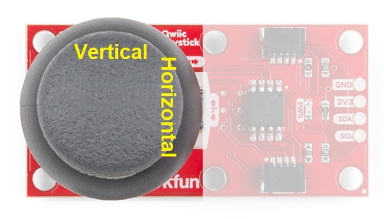
The potentiometers are the two blue or black boxes on the sides of the joystick. If you move the joystick while watching the center shaft of each potentiometer, you'll see that each of the potentiometers will pick up movement on only one axis. Clever, isn't it?
Select Button
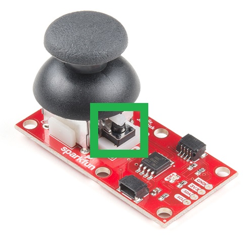
The joystick also contains a momentary button which activates when you push down on the cap. The button is the small black box on the side of the joystick. If you push down on the cap, you can see a lever pushing down on the head of the button. The lever works no matter what position the joystick is in. That is pretty cool!
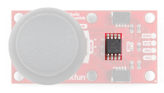
ATtiny85
With the pre-installed firmware, the ATtiny85 is acts as an intermediary (microcontroller) for the analog and digital inputs from the joystick. This allows the Qwiic Joystick to report its position over I2C.
Qwiic & I2C
I2C Address
In the firmware, the Qwiic Joystick’s I2C address is configurable so you can add a bunch of them to the same bus without collision issues.
Factory Default I2C Slave Address: 0x20
I2C Registers
| Address | Description |
|---|---|
| 0x00 | Default I2C Slave Address from EEPROM |
| 0x01 - 0x02 | Firmware Version (MSB First) |
| 0x03 - 0x04 | Current Horizontal Position (MSB First) |
| 0x05 - 0x06 | Current Vertical Position (MSB First) |
| 0x07 | Current Button Position |
| 0x08 | Button Status: Indicates if button was pressed since last read of button state. Clears after read. |
| 0x09 | Configuration or "Locking" Register - Prevents random I2C address changes during I2C scans and register dumps. Must be set to 0x13 before an address change gets saved to the EEPROM. |
| 0x0A | Current/Set I2C Slave Address (Write). Stored in EEPROM. |
uint_16t full10bitvalue = ((MSB << 8) | LSB) >> 6;
You could potentially only look at the MSB and get an 8-bit reading (for 256 positions). The firmware was intentionally written this way in the hopes that it would be useful for customers who didn't need the full resolution of the joystick position.
Please be aware, the first time the joystick position registers are read, it will have a maximum value (all 1's in binary). I am not sure if it is something in the firmware or if has something to do with the ATtiny85, but the initial read will be 1023. Once that is read, everything reading after should be accurate (excluding the manufacturing tolerances mentioned above). If you have a fix for this issue, please feel free to comment on this tutorial or create a pull request on the GitHub repository.
Connections
The board provides four labeled breakout pins. You can connect these lines to the I2C bus of your microcontroller and power pins (3.3V and GND), if it doesn't have a Qwiic connector.
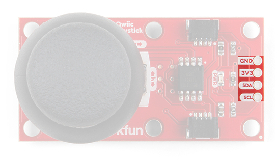
However, the simplest way to use the Qwiic Joystick is through the Qwiic connect system. The connectors are polarized for the I2C connection and power. (*They are tied to the breakout pins.)
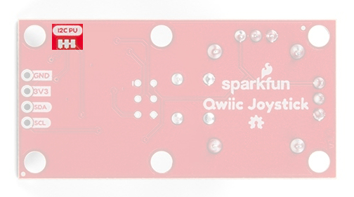
I2C Pull-up Jumpers
Cutting the I2C jumper will remove the 2.2kΩ resistors from the I2C bus. If you have many devices on your I2C bus you may want to remove these jumpers. Not sure how to cut a jumper? Read here!