Qwiic Haptic Driver DA7280 Hookup Guide
 bboyho,
  Elias The Sparkiest
Hardware Overview
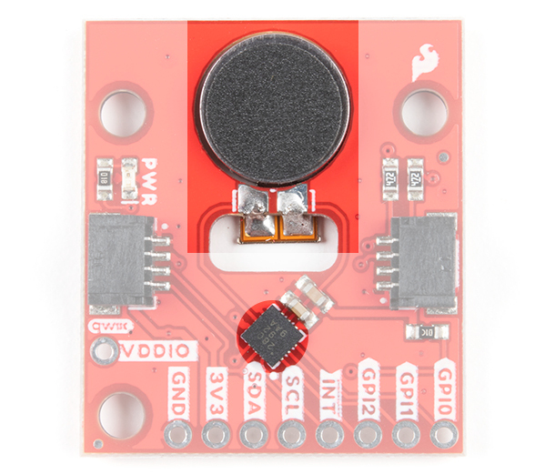
Haptic Driver and LRA Motor
The haptic driver IC rotated at 45° with respect to the board while the circular disk is the LRA motor. If you received the kit version, the motor will need to be soldered to the board using the wires. Note that the Arduino library used in this tutorial configures the DA7280's settings based on the LRA motor's specifications.
Power and Logic Levels
We recommend powering the board through the Qwiic connector when quickly prototyping. For a more secure connection, you can always solder to the PTHs labeled 3V3/VDD and GND. The recommended input voltage when using the board with a microcontroller is 3.3V. However, you could potentially power the board between 2.8V to 5.5V as explained in the datasheet. Note that the 3V3/VDD is connected to VDDIO. There is a jumper on the back of the board to disconnect the input voltage and the logic levels if you decide to use different voltages. If you decide to adjust the logic level, this is typically 1.8V. However, you can set the logic levels between 1.35V and 5.5V as long as VDDIO ≤ VDD and if GPI0, GPI1, and GPI2 are not grounded as it is recommended in the datasheet.
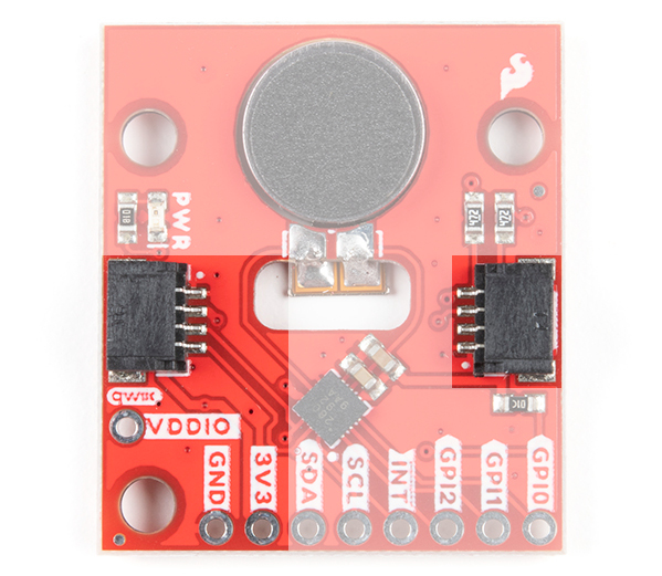
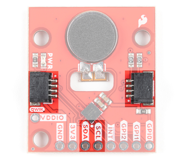
I2C
The main method of controlling the DA7280 and the vibe motor is through the I2C bus. The board includes two Qwiic connectors for fast prototyping and removes the need for soldering. All you need to do is plug a Qwiic cable into the Qwiic connector and voila! You can also solder to the PTHs labeled as SDA and SCL as an alternative. The address for the DA7280 is 0x4A.
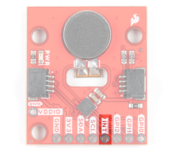
Interrupt
The interrupt is active low and notifies the host microcontroller when the DA7280 has finished driving the motor. This connection is optional and available for those that decide to include an interrupt for their application.
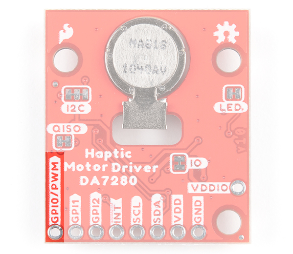
PWM Pin
The second method of controlling the DA7280 is to send a PWM signal to the GPI0 pin. Once the DA7280 is configured to PWM mode via I2C, the duty cycle of the PWM signal will be reflected on the DA7280's output drive to the vibration motor. The DA7280 requires that the PWM signal is at least 10kHz. The top of the board only labels the PTH as GPI0 due to the space available around the pin while the back of the board labels the pin as GPI0/PWM.
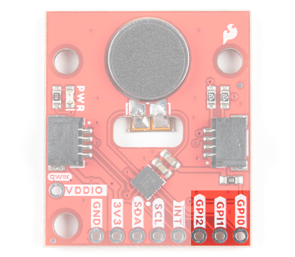
GPI Pins
The third method of controlling DA7280 and the motor is through the general purpose input (GPI) pins. These can be configured to edge trigger based on the the combination of the pins and waveforms that are stored in the DA7280's memory.
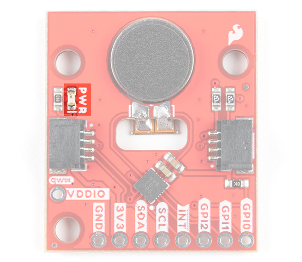
LED
The board includes an LED indicator that lights up when there is power available.
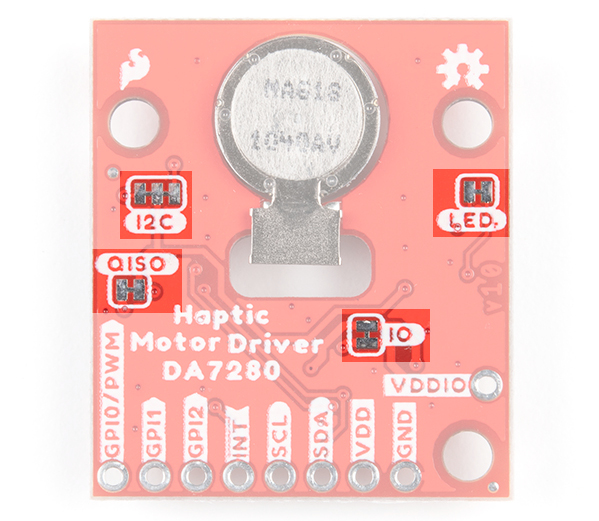
Jumpers
There are four jumpers on the back of the board. For more information, check out our tutorial on working with jumper pads and PCB traces should you decide to cut the traces with a hobby knife.
- LED - This is connected to the PWR LED on the top of the board. Cutting this disables the LED.
- I2C - The I2C jumper is connected to the 4.7kΩ pull-up resistors for the I2C bus. Most of the time you can leave these alone unless your project requires you to disconnect the pull-up resistors.
- QISO - The QISO jumper is connected to the Qwiic bus power line (i.e. 3.3V). Cut this trace to separate power from the Qwiic ports if you decide to power the board with a different voltage on 3V3/VDD. Note that the I2C lines are still pulled up to 3.3V.
- IO - The IO jumper connects 3.3V/VDD to VDDIO for the DA7280. Cut this trace and supply VDDIO with a different voltage to adjust the DA7280's logic levels. This is typically 1.8V. However, you can set the logic levels between 1.35V and 5.5V as long as VDDIO ≤ VDD and if GPI0, GPI1, and GPI2 are not grounded as it is recommended in the datasheet
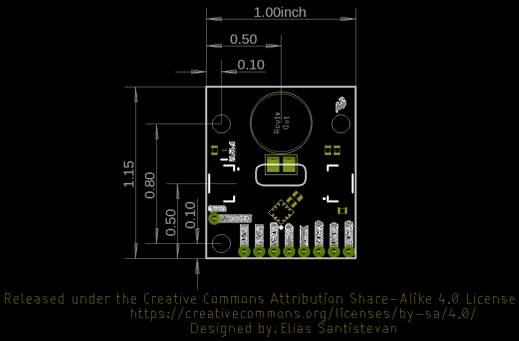
Board Dimensions
The board dimension is 1.00" x 1.15" and includes 3x mounting holes. The mounting holes are spaced using the Qwiic standard for 1.0"x1.0" sized boards. Note that the board is longer on one side to accommodate the SMD vibe motor.