Qwiic Haptic Driver DA7280 Hookup Guide
 bboyho,
  Elias The Sparkiest
Hardware Assembly
There are three modes (I2C, PWM, and stande-alone with the GPI) available for the DA7280. For the scope of this tutorial and Arduino Library, we will be using the I2C and PWM modes. If you are using the PTHs, we recommend soldering header pins or wires to the board for a secure connection.
I2C Mode
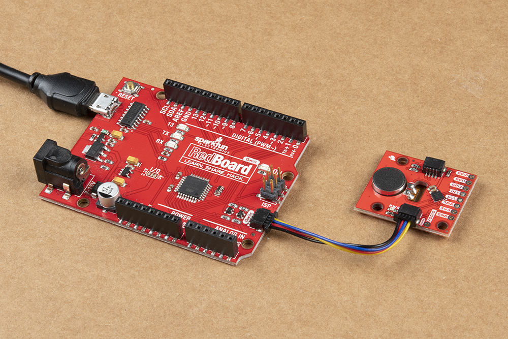
The main method to control the DA7280 is through an I2C bus. You'll need the RedBoard Qwiic and a USB cable to program the microcontroller. Insert the USB cable into the RedBoard. Then insert a Qwiic cable between the RedBoard Qwiic and Qwiic Haptic Driver. Depending on your application, you can also solder to the plated through holes for a secure connection.
PWM Mode
The second method of controlling the DA7280 is via PWM. The Haptic Driver IC requires that the PWM signal frequency given to GPI0/PWM pin is at least 10kHz. The default PWM methods of analogWrite() does not provide a method of controlling the frequency of the PWM signal. To use with the RedBoard with ATmega328P, you will need to use the TimerOne Arduino Library by Paul Stoffregen as explained later in this tutorial. Note that this library is limited to certain boards. For the Arduino Uno (e.g. the RedBoard with ATmega328P) the pins that are reserved for PWM are on pins 9 and 10.
In this case, we will connect the Qwiic Haptic's GPIO0/PWM pin to the RedBoard's pin 9. We also still need to control the DA7280. Make sure to include a Qwiic cable between the boards as well.

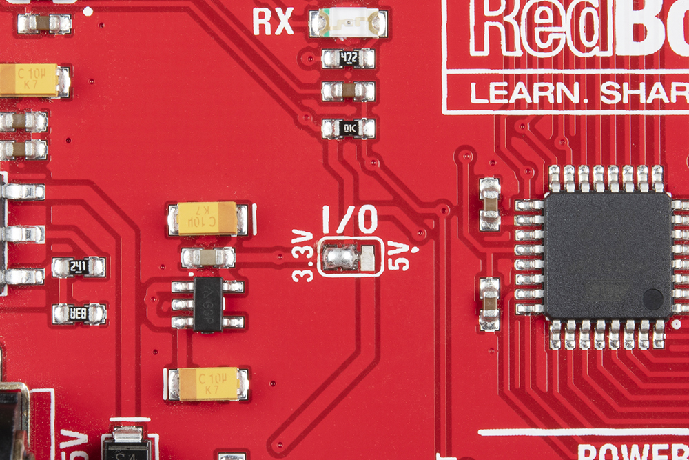
Before powering up, you will also need to ensure that you cut the trace for the RedBoard Qwiic's I/O and add a solder jumper to the 3.3V pin.
Soldering Wires
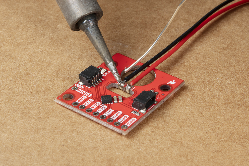
For those that want to attach the LRA motor separately from the board, you will need to solder wires between the Qwiic Haptic Driver board's castellated pins. For a flush connection, we recommend cutting the male header pins and stripping the wire. Solder the black wire to the castellated pin (which is connected to DA7280's OUTN pin) that is the closest to the PWR LED. Then solder the red wire to the other castellated pin (which is connected to the DA7280's OUTP pin).
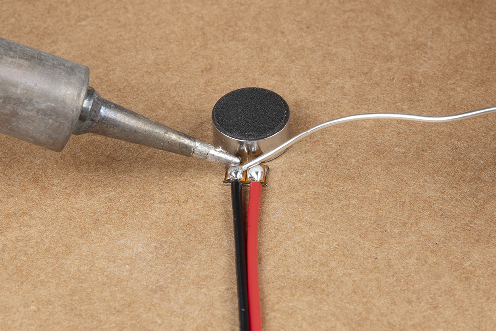
Cut and strip the wire on the other ends. With the LRA motor's SMD pads facing you (as shown in the image below), solder the black wire on the left pad. Then solder the red wire on the right pad.
If you decide to leave the header pins on the wires, your setup will look similar the image on the left. With the header pins removed, your setup will look similar to the image on the right. For a secure connection, you may want to add some hot glue to the terminals for strain relief. Once soldered, simply attach a Qwiic cable between the Qwiic connectors or solder wire to your connections as explained above. Remember, you will need to adjust the RedBoard Qwiic's logic level to 3.3V if you decide to use the PWM mode.
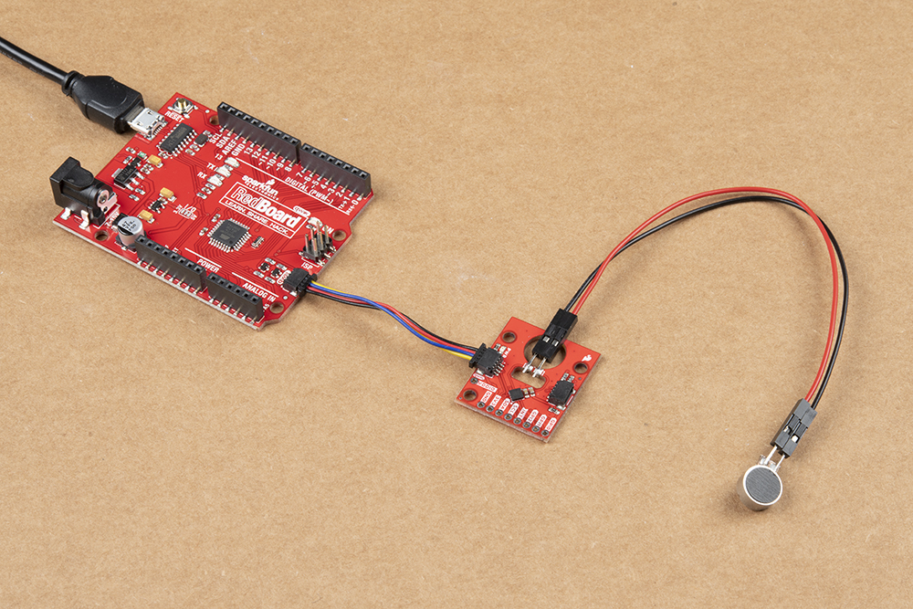 |
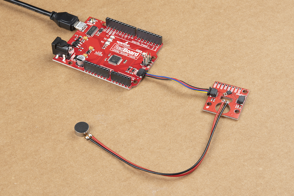 |
| M/M jumper wires soldered | M/M jumper pins cut and wire soldered |