Qwiic Differential I2C Bus Extender (PCA9615) Hookup Guide
 Joel_E_B,
  Alex the Giant
Hardware Overview
The simplicity of the Qwiic differential I2C breakout is one of its biggest appeals. Other I2C communication methods require packetizing I2C communication into another protocol, be it RS-485 or 1-Wire. However, the PCA9615 keeps the I2C protocol by utilizing a differential transceiver. In this section, we'll take a closer look at the board to better understand how it works.
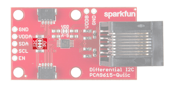
Pinout
Below are the plated through hole pins that are broken out on the board. The I2C pins are connected to the two Qwiic connectors on the sides.
PTH Connections
- GND - Ground
- VDDA - 2.3VDC to 5.5VDC. I2C-bus side power supply.
- VDDB - 3.0VDC to 5.5VDC. Differential side power supply. If jumper "VDD A-B" is not shorted, then VDDB will need to be powered for the differential I2C bus to operate.
- SDA - I2C data signal.
- SCL - I2C clock signal.
- EN (optional) - PCA9615 enable (active high, internally pulled up). This is used to disable the bus buffer, and is useful for fault finding, power-up sequencing, or reconfiguration of a large bus system by isolating sections not needed at all times.
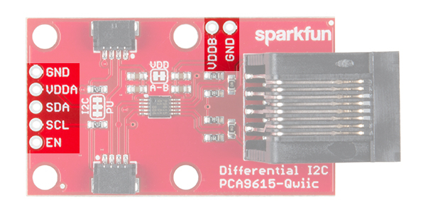
Qwiic Connections
- GND - Ground.
- VDDA - 2.3VDC to 5.5VDC. I2C-bus side power supply. If "VDD A-B" is not shorted, VDDB will need to powered separately for the differential I2C bus to operate.
- SDA - I2C data signal.
- SCL - I2C clock signal.
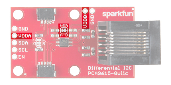
VDDA vs VDDB
To power the board, VDDA must be present and be the same logic voltage as the SDA/SCL lines, while VDDB is used to power the differential I2C bus. By default, the jumper labeled "VDD A-B" is closed, which connects the VDDA rail to the VDDB rail. By cutting the jumper you can separate the two rails which would allow for one rail to operate at 3.3V while the other can operate at 5V.
VDDB and Ground Jumpers
If the number of sensors connected on the other side of the extended I2C bus is minimal, you can power them over the Ethernet cable. However, if there are numerous sensors connected, it is advised that both ends be powered separately. To isolate the power supplies at both ends of the Ethernet cable, use a sharp blade to cut the small traces betweens the pads of the jumpers labeled "VDDB" and "GND". VDDB will still be present on each board, but the Ethernet cable will not carry any current to power a device at the other end of the cable.
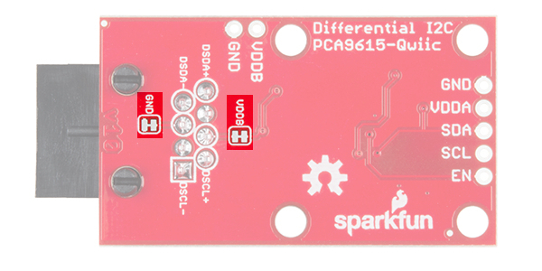
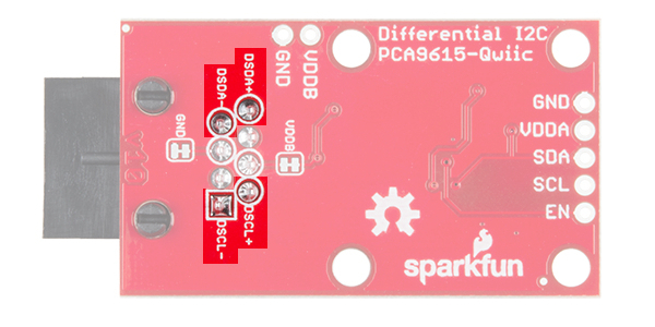
Differential Signals
From the bottom of the board, we can see which pins the RJ-45 connector uses for the differential signaling. The board has been designed to use a standard Ethernet cable. If a custom cable is made, make sure to connect a twisted pair for pins 1 and 2 (DSCL-, DSCL+) and pins 7 and 8 (DSDA-, DSDA+).
I2C Pull-Up Resistors
As with most SparkFun I2C products, there is a jumper for the pull-up resistors on the I2C bus. If multiple sensors are connected to the bus with the pull-up resistors enabled, the parallel equivalent resistance will create too strong of a pull-up for the bus to operate correctly. As a general rule of thumb, disable all but one pair of pull-up resistors if multiple devices are connected to the bus.