Qwiic Ambient Light Sensor (VEML6030) Hookup Guide
 Elias The Sparkiest
Hardware Overview
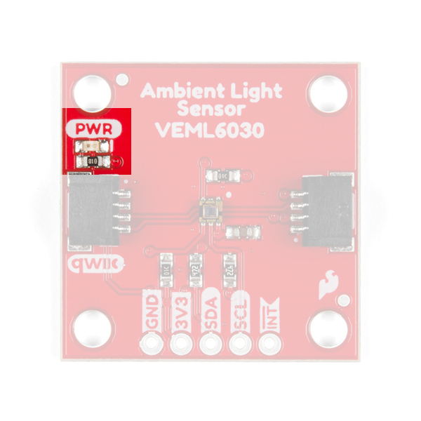
Power
You can provide 3.3V through the Qwiic connector on the board or through the 3V3 labeled pin on the through hole header. When you correctly power the board, the on-board red power LED will turn on.

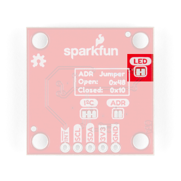
LED
There is one red LED on the product that will turn on when power is supplied to the board. You can disconnect this LED by cutting the jumper on the underside of the product labeled LED, see Jumpers below.
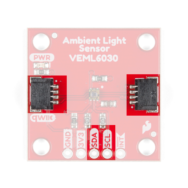
Qwiic Connector or I2C Pins
There are two Qwiic connectors on the board to easily connect to the sensor via I2C. Another option is to solder directly to the I2C plated through holes on the side of the board. We have many Qwiic sensors and Qwiic enabled micro-controllers. Check out our Qwiic Ecosystem page to get a glimpse of what else we have to offer.
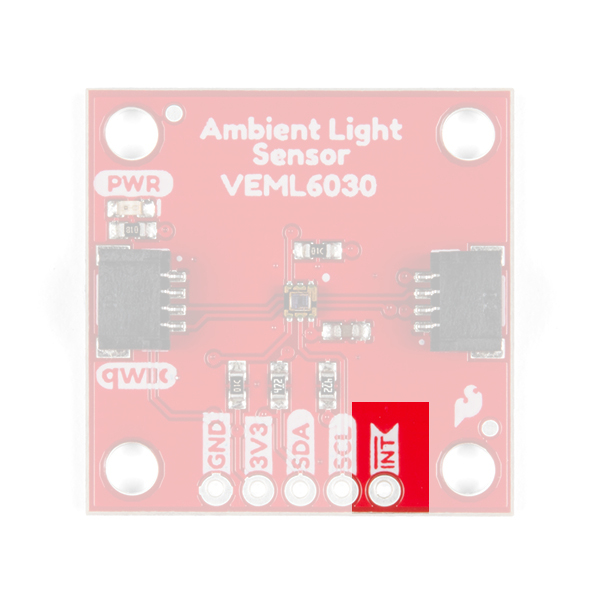
Interrupt Pin
A nice feature on the SparkFun Ambient Light sensor is its ability to set both LOW and HIGH thresholds that triggers an interrupt on the product. For example, we can know when the light in a room falls below a certain amount and conversely when the light comes back on! You don't have to settle for just the hardware interrupt though. We also have a software solution, check out the interrupt example code below.
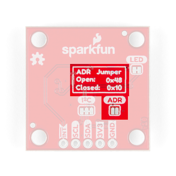
Jumpers
There are three jumpers on the underside of this board. Starting in the lower left is a triple jumper labeled I2C that connects pull-up resistors to the I²C data lines. If you're daisy chaining many I²C devices together than you may need to consider cutting these traces.
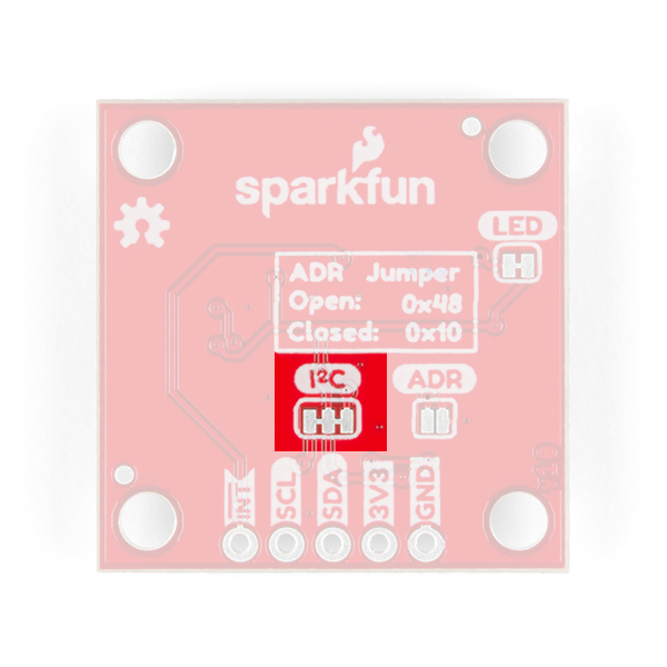
To the right of that is the address jumper labeled ADR that allows you to select the SparkFun Ambient Light Sensor's other I²C address: 0x10. By default your SparkFun Ambient Light Sensor is shipped with the I²C address 0x48.
Finally the jumper in the upper right is the LED jumper which can be cut to disconnect the on board power LED.
Gain and Integration Time Settings
What does gain and integration time mean? You can think of gain as an electronic mechanism to amplify a weak signal. If you're in a dark room with very little light, the sensor needs a way to amplify the weak light source to get accurate lux calculations and the gain is what give is it's oomph. Likewise, Integration time is the amount of time the sensitive photo diodes within the sensor absorb light before beginning its' Lux calculation. Both of these together are necessary for sensing in a dark room, but what if it was really bright outside?! Now there's so much light in the envinronment that you actually want to scale down the electronic's response to that saturation so you need a lower gain. And since there's so much light, the photo diodes don't need to be exposed long to get what they need to make the calculations, so a lower integration time is also needed.
The SparkFun Ambient Light Sensor can detect ranges of light in Lux from zero to 120,796! That's a gigantic range from dark to direct sun in the middle of the day. To accomplish this you have to set the Gain and Integration Time settings. This is trivial with the Arduino Library we've written and we'll walk you through it below in Example1 Ambient Light Basics. With each setting gives you a range of light that you can read. Check out the table below to see what's capable at each possible setting. Notice that slower integration and higher gain gives you a smallest range of (0->236) but the highest resolution (0.0036 lux/bit).
Maximum Light Detection Range: Lux
| Integration Time (milliseconds) | GAIN 2 | GAIN 1 | GAIN 1/4 | GAIN 1/8 |
|---|---|---|---|---|
| 800 | 236 | 472 | 1887 | 3775 |
| 400 | 472 | 944 | 3775 | 7550 |
| 200 | 944 | 1887 | 7550 | 15099 |
| 100 | 1887 | 3775 | 15099 | 30199 |
| 50 | 3775 | 7550 | 30199 | 60398 |
| 25 | 7550 | 15099 | 60398 | 120796 |
Resolution: Lux/Bit
| Integration Time (milliseconds) | GAIN 2 | GAIN 1 | GAIN 1/4 | GAIN 1/8 |
|---|---|---|---|---|
| 800 | 0.0036 | 0.0072 | 0.0288 | 0.0576 |
| 400 | 0.0072 | 0.0144 | 0.0576 | 0.1152 |
| 200 | 0.0144 | 0.0288 | 0.1152 | 0.2304 |
| 100 | 0.0288 | 0.0576 | 0.2304 | 0.4608 |
| 50 | 0.0576 | 0.1152 | 0.4608 | 0.9216 |
| 25 | 0.1152 | 0.2304 | 0.9216 | 1.8432 |
Power Save Modes
Another cool feature of the SparkFun Ambient Light Sensor is its ability to run at extremely low currents. Power save modes should be used when you're continuously reading ambient light data. For example, if you're going to gather ambient light data every second, why not use a power save mode and save battery life? There are four power save modes that can be enabled with integration times of 100ms and above. Below is a table showing the power save mode, the current draw, and it's refresh rate. Check out Example 4 in the Arduino Library to see how to set it up and use the table below as a reference.
| Integration Time | Power Save Mode | Refresh Time (milliseconds) | Current Draw (microamperes) | Resolution (lx/bit) |
|---|---|---|---|---|
| 100 | 1 | 600 | 8 | 0.0288 |
| 100 | 2 | 1100 | 5 | 0.0288 |
| 100 | 3 | 2100 | 3 | 0.0288 |
| 100 | 4 | 4100 | 2 | 0.0288 |
| 200 | 1 | 700 | 13 | 0.0144 |
| 200 | 2 | 1200 | 8 | 0.0144 |
| 200 | 3 | 2200 | 5 | 0.0144 |
| 200 | 4 | 4200 | 3 | 0.0144 |
| 400 | 1 | 900 | 20 | 0.0072 |
| 400 | 2 | 1400 | 13 | 0.0072 |
| 400 | 3 | 2400 | 8 | 0.0072 |
| 400 | 4 | 4400 | 5 | 0.0072 |
| 800 | 1 | 1300 | 28 | 0.0036 |
| 800 | 2 | 1800 | 20 | 0.0036 |
| 800 | 3 | 2800 | 13 | 0.0036 |
| 800 | 4 | 4800 | 8 | 0.0036 |
Rounding Errors?!
Later on when you read back an interrupt threshold, you may notice that the interrupt lux values are off by one in some cases. This is because of the inherent rounding error with the Ambient Light Sensor. The final Lux value is calculated by multiplying the value of the bits that represent the ambient light by a decimal number (0.2304 for example). This decimal number is rounded to a whole number (e.g. 19.97 becomes 19) because the sensor does not care about fractions of a Lux. I chose to read back the rounded number because that's the interpreted value of the ambient light sensor and what is stored in its' registers.